
End effector coupler for surgical arm

a technology of end effector and surgical arm, which is applied in the field of end effector coupler for surgical arm, can solve the problems of undesirable manual holding of instruments

Active Publication Date: 2019-09-12
ZIMMER BIOMET CMF & THORACIC
View PDF5 Cites 10 Cited by
  • Summary
  • Abstract
  • Description
  • Claims
  • Application Information

AI Technical Summary

Problems solved by technology

Because it may be difficult or undesirable to manually hold a position of an instrument for such lengths of time, mechanical and

Method used


Image

  • End effector coupler for surgical arm
  • End effector coupler for surgical arm
  • End effector coupler for surgical arm

Examples


examples

[0170]The following, non-limiting examples, detail certain aspects of the present subject matter to solve the challenges and provide the benefits discussed herein, among others.

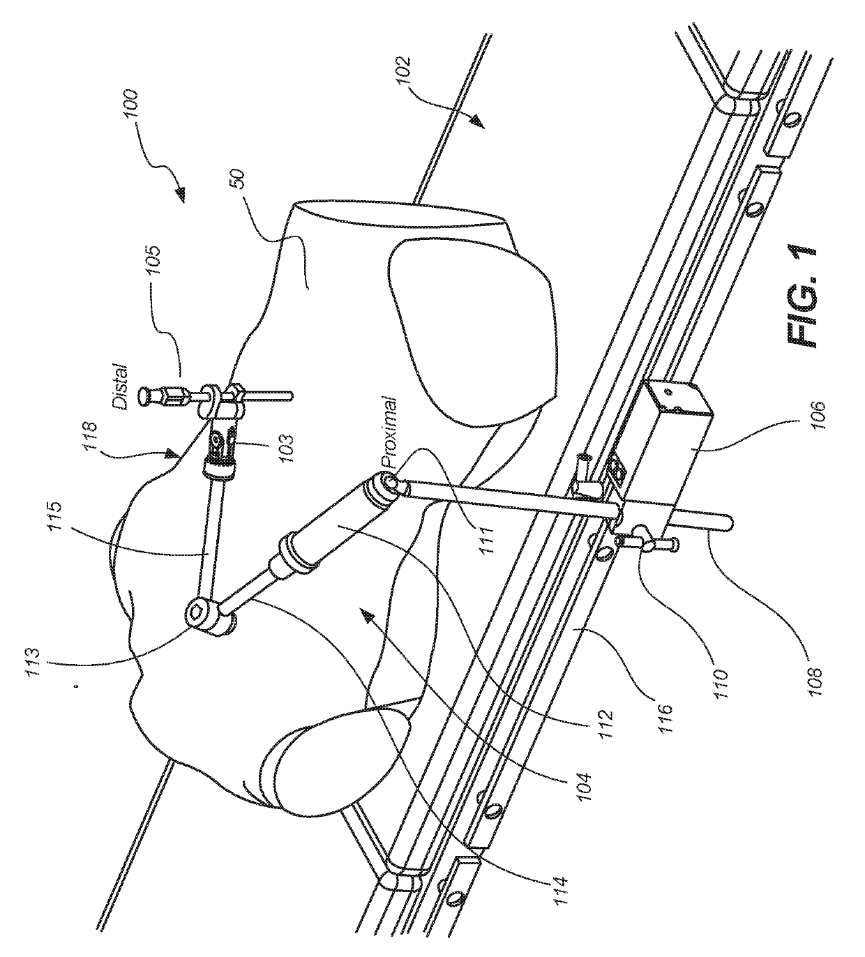
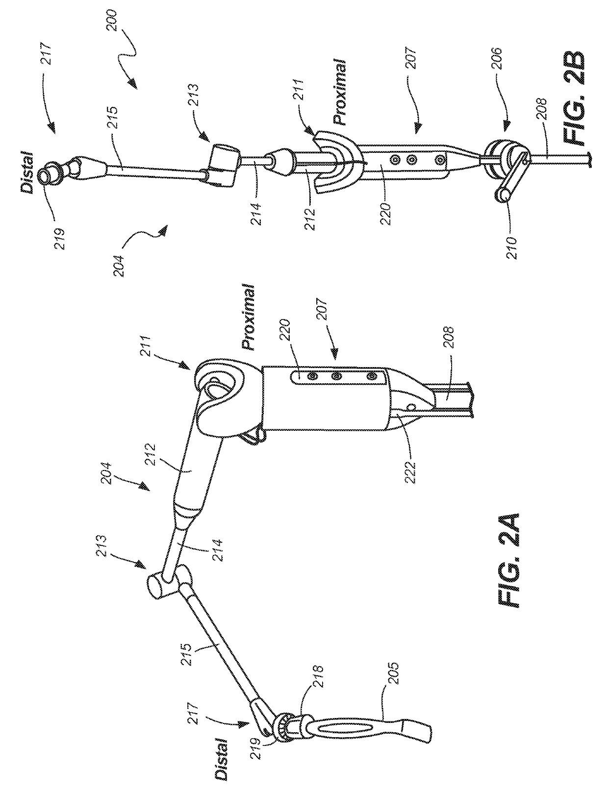
[0171]Example 1 is a system for a surgical arm, the system comprising: a body comprising a proximal portion and an opposite distal portion, the distal portion including a distal end; a control device couplable to an external surface of the body and operable to transmit a signal to allow movement of the surgical arm.

[0172]In Example 2, the subject matter of Example 1 optionally includes wherein the pin limits rotation of the stem relative to the keyed opening to prevent release of the stem from the keyed opening when the pin engages the stem.

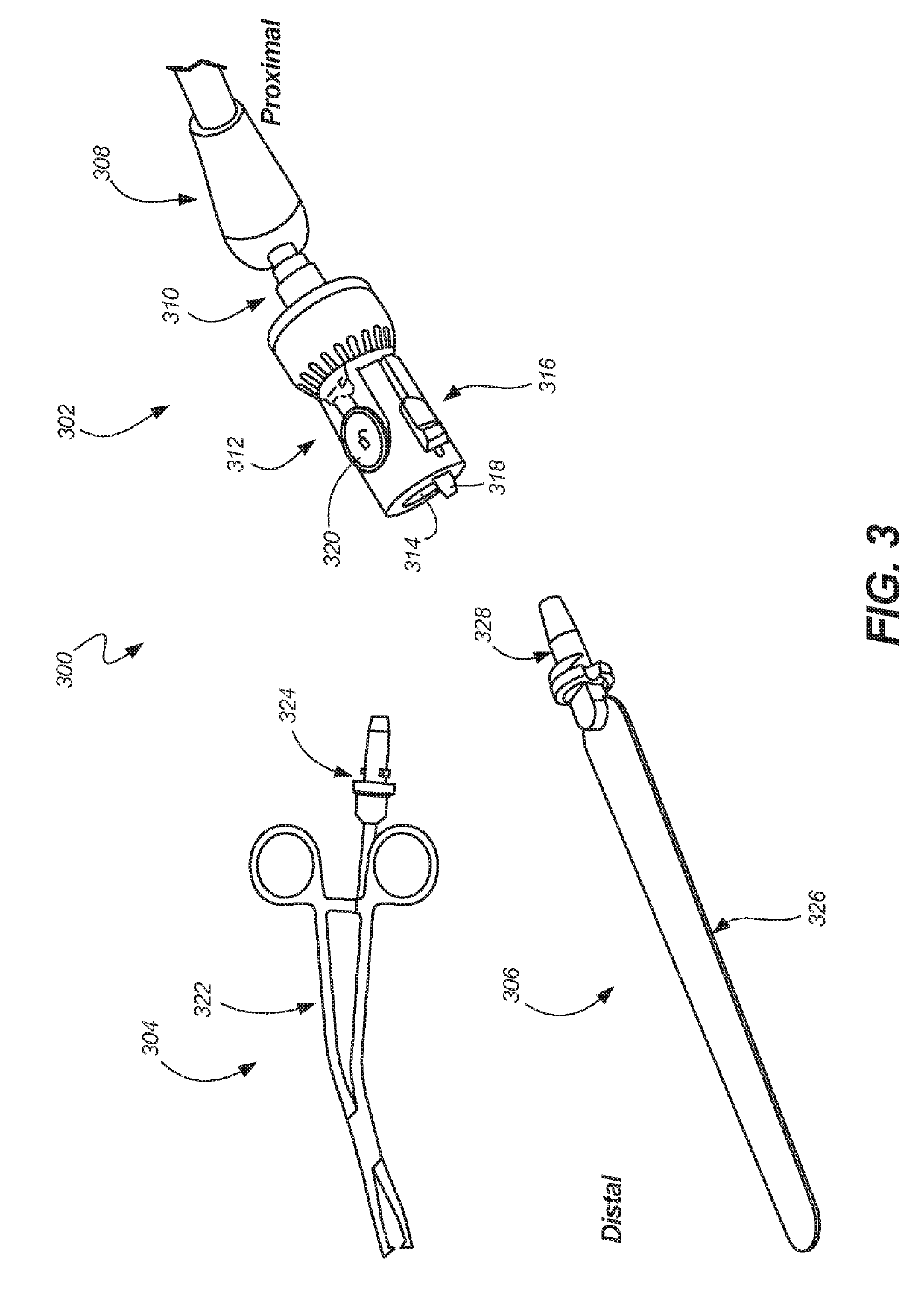
[0173]In Example 3, the subject matter of any one or more of Examples 1-2 optionally include wherein the body includes a tapered bore aligned along a central axis running through the keyed opening and configured to receive the tool stem therein.

[0174]In Example 4, the subj...


PUM


Abstract

An end effector coupler for a surgical arm can include a body, a proximal coupler, and a tool lock. The tool lock can releasably retain a tool stem to the end effector coupler. The tool lock can include a keyed opening, a pin bore, a pin disposed in the bin bore, a biasing element located in the pin bore, and a pin release including an actuator, the pin release operable to retract the pin into to the body to disengage the pin from the tool stem allowing release of the tool stem from the keyed opening.

Description

CROSS-REFERENCE TO RELATED PATENT DOCUMENTS[0001]This patent application is also related to Jeffrey Schlosser et al., U.S. patent application Ser. No. 15 / 560,894 entitled “Rapidly Repositionable Powered Support Arm,” filed on Sep. 22, 2017 which is hereby incorporated by reference herein in its entirety.BACKGROUND[0002]The present invention relates generally to apparatus and systems for supporting surgical and other instruments. Some surgical procedures include use of a variety of instruments. In some of these procedures, it is required that instruments, such as a retractor, be maintained in a single position for an extended period of time, such as an hour or more. During this time, other instruments can be used to perform other aspects of the surgery. Because it may be difficult or undesirable to manually hold a position of an instrument for such lengths of time, mechanical and / or electromechanical arms can be used to hold the position of the instrument while other aspects of the p...

Claims


Application Information

Patent Timeline
IPC IPC(8): A61B90/50
CPCA61B2090/571A61G13/101F16M11/06A61B90/50A61B2017/00477
Inventor BILLARD, MAX HOLLANDLUBY, RYANROBINSON, SHAWNWITTEN, BENJAMINFRANK, ZACHARYBRUNEAU, AURELIENBONIFACE, CATHERINEGARCIA, SADDYCARLTON, ROBERTPAUL, RALPHSIACHAMES, DEMETRIUS
Owner ZIMMER BIOMET CMF & THORACIC
Features
  • Generate Ideas
  • Intellectual Property
  • Life Sciences
  • Materials
  • Tech Scout
  • Unparalleled Data Quality
  • Higher Quality Content
  • 60% Fewer Hallucinations
Learn More