Coating for the concealment of objects from the electromagnetic radiation of antennas

Active Publication Date: 2019-10-31
AIRBUS SAS
View PDF0 Cites 3 Cited by
  • Summary
  • Abstract
  • Description
  • Claims
  • Application Information

AI Technical Summary

Benefits of technology

[0015]The device according to the invention provides an effective and ec

Problems solved by technology

The solutions presented above have the following drawbacks: their geometry and/

Method used


Image

  • Coating for the concealment of objects from the electromagnetic radiation of antennas
  • Coating for the concealment of objects from the electromagnetic radiation of antennas
  • Coating for the concealment of objects from the electromagnetic radiation of antennas

Examples


Embodiment Construction

[0047]Throughout the description, with the exception of the equations, in the same way as in the drawings, vectors are shown in bold so as to facilitate notation.

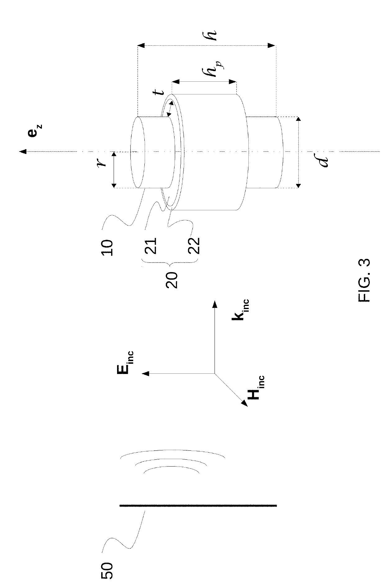
[0048]The components of a vector are identified by means of their coordinates in subscript, for example a vector E is defined in terms of Cartesian coordinates by its components (Ex, Ey, Ez) and in terms of cylindrical coordinates by its components (Ep, Eθ, Ez).

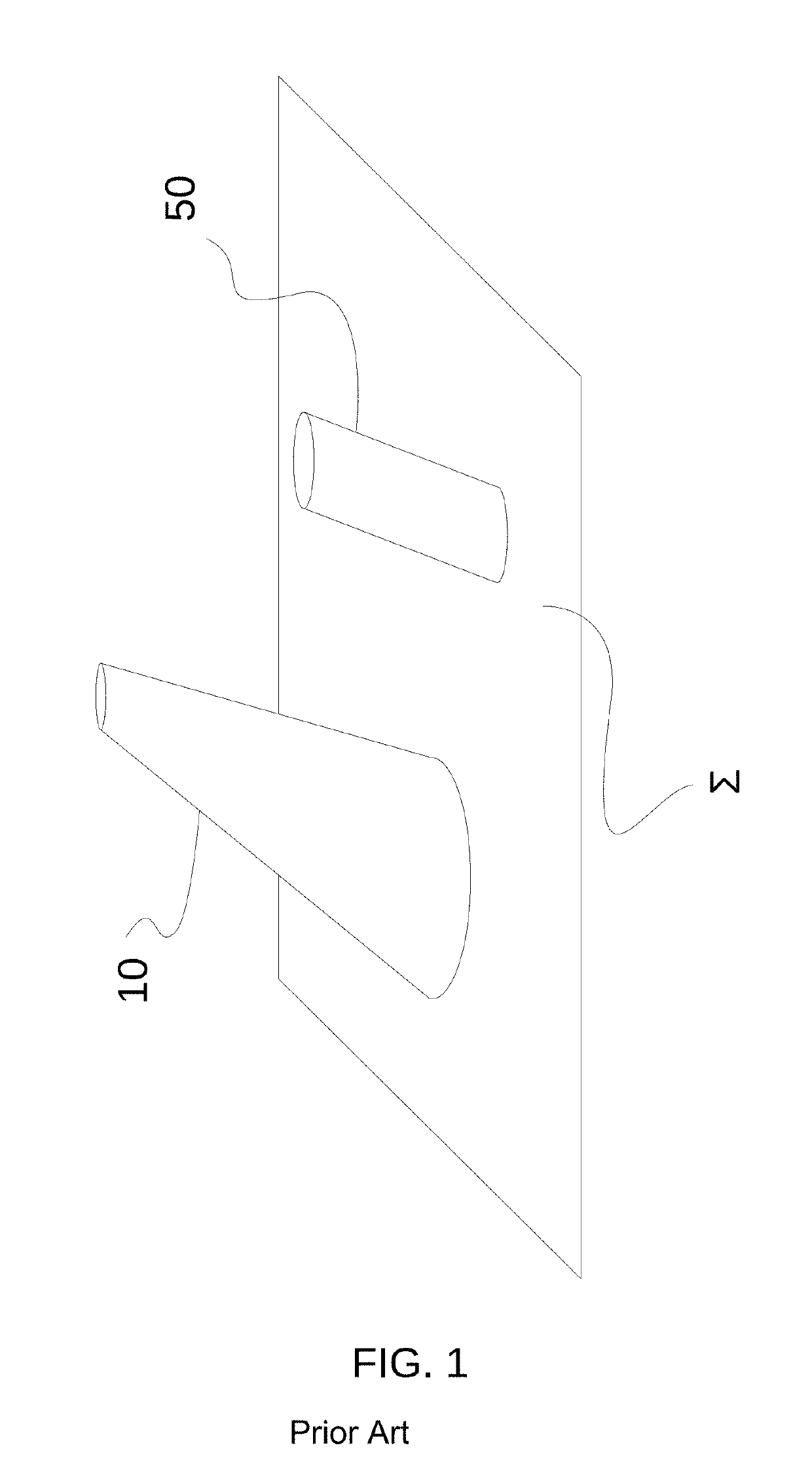
[0049]When an orthonormal coordinate system (O; ex; ey; ez) is defined, the vertical direction will be designated as that given by the axis ez. This results from an arbitrary choice based on a commonly held convention, and does not limit the invention. As such, any plane parallel to the plane (O; ex; ey) is considered to be a horizontal plane.

[0050]The acronym EMW will be used throughout the description to refer to an electromagnetic wave. When this EMW has a wavelength λ, any physical quantity a having the dimension of a length could be rendered dimensionless with r...


PUM


Abstract

An assembly comprising a device and an obstacle subjected to an incident electromagnetic wave of wavelength λ. The obstacle is formed from an electrically conductive material and has a substantially cylindrical shape of transverse dimensions r with respect to a longitudinal axis (O, ez). The longitudinal axis is substantially perpendicular to a propagation direction of the incident electromagnetic wave. The obstacle further has a maximum transverse dimension d such that the ration λ/d is less than 1. The device is placed on all or a part of a surface of the obstacle and comprises a sleeve with a dielectric coating of equivalent relative permittivity EREQ, of height hP along a longitudinal axis of the sleeve, substantially equal to formula A, and a sleeve with an electrically conductive coating placed on the periphery of the dielectric coating.

Description

CROSS-REFERENCES TO RELATED APPLICATIONS[0001]This application claims the benefit of the International Application No. PCT / FR2017 / 052938, filed on Oct. 24, 2017, and of the French patent application No. 1660282 filed on Oct. 24, 2016, the entire disclosures of which are incorporated herein by way of reference.FIELD OF THE INVENTION[0002]The present invention pertains to the field of electromagnetism.[0003]More particularly, the invention pertains to the field of antennas.[0004]More particularly, the invention relates to a device for attenuating the effects of an obstacle on the radiation characteristics of a radio antenna.BACKGROUND OF THE INVENTION[0005]Generally, the presence of a conductive obstacle in an electromagnetic field gives rise to variations in the electromagnetic field, for example a phase shift, which variations reveal the presence of the obstacle.[0006]When such an object is located in proximity to a radio antenna, see FIG. 1, it generally results in the radiation pa...

Claims


Application Information

Patent Timeline
IPC IPC(8): H01Q17/00H01Q1/32H01Q1/38
CPCH01Q1/38H01Q17/00H01Q1/3233H01Q1/28H01Q1/52H01Q19/021
Inventor PIAU, GÉRARD-PASCALDE LUSTRAC, ANDRÉBORISSOV, TATIANA
Owner AIRBUS SAS
Why Eureka
Try Eureka