Crop Row Mower

a mower and row technology, applied in the field of crop row mowers, can solve the problems of difficult and difficult configuration of mowing, mechanical complexity and cumbersome, and only being manufactured at great expens

Active Publication Date: 2019-11-14
BUTTON BARBARA J
View PDF0 Cites 4 Cited by
  • Summary
  • Abstract
  • Description
  • Claims
  • Application Information

AI Technical Summary

Benefits of technology

[0006]A wheel is preferably rotatably mounted at the distal end of the “L” member's foot, allowing the “L” member to be either rollably pushed or pulled by mechanized equipment along a crop row space. In the preferred embodiment, the rotatable attachment of the wheel includes an adjustable swivel arm assembly which allows the wheel to be selectively vertically positioned in relation to the distal end of the foot. Such wheel adjustability feature advantageously allows the height of the “L” member, along with its weed cutting blades, discussed below, to be operated at a selected weed cutting height.
[0012]In operation of the instant inventive crop row mower, several renditions of the mower are preferably provided, each mower being fixedly attached to a self-propelled vehicle boom arm, as described above. The several renditions of the crop row mower are preferably spaced along the boom arm at intervals which coincide with the spacing of the crop rows to be mowed. Actuation of the motor means effectively rotates and counter-rotates each motor's rotary blades, allowing for progressive weed cutting while the row mowers are driven or pulled along the spaces between crop rows. During the mowers' weed cutting operation along and between the crop rows, the wheel components at the distal ends of the “L” members' feet effectively roll behind the weed cutting blades while consistently holding the blades at a pre-selected and appropriate elevation over the ground.

Problems solved by technology

The geometry of crop rows gives rise to difficulties and challenges in the configuration of mowing equipment for cutting of weeds growing between the crop rows.
Mowing equipment which is capable of extending downwardly between multiple crop rows for mowing narrow swathes of weeds, and without damage to adjacent crops, is often mechanically complex and cumbersome, and often is manufactured only at great expense.

Method used


Image

  • Crop Row Mower
  • Crop Row Mower
  • Crop Row Mower

Examples


Embodiment Construction

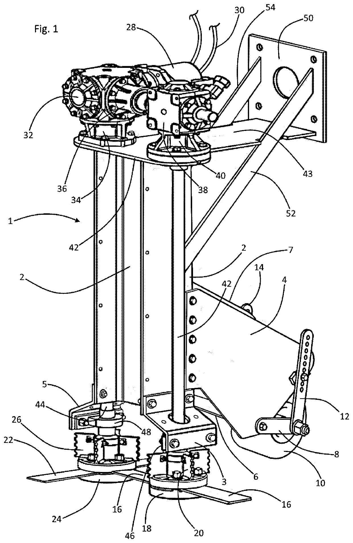
[0019]Referring now to the drawings and in particular to Drawing FIG. 1, a preferred embodiment of the instant inventive crop row mower is referred to generally by Reference Arrow 1. The crop row mower 1 preferably comprises an “L” member which, similarly with the structure of a common capital letter “L”, has a column portion 2, and has a foot portion 4 and 7. The foot 4, 7 is fixedly attached to and extends rearwardly or distally from the column portion's lower end. In a preferred embodiment, the “L” member's foot 4, 7 comprises left and right steel plates whose proximal ends are fixedly welded or bolted (as depicted) to left and right flanges of the “I” beam configured column 2. A cross brace 6 spans between plates 4 and 7 in order to enhance the foot component's structural rigidity. Suitably, the “I” cross sectional shape of the column 2 may be produced via a double “C” channel beam weldment (not shown in views) having abutting webs.

[0020]A wheel 10 is preferably mounted by a rot...


PUM


Abstract

A crop row mower incorporating an “L” member having a column and having a foot, the column having upper and lower ends, and the foot having a distal end; a wheel connected operatively at the distal end of the foot; a first rotary blade mounted at the lower end of the column; a hydraulic motor mounted at the upper end of the column; a first drive shaft extending along the column, the first drive shaft operatively interconnecting the hydraulic motor, and the first rotary blade; and a mounting bracket fixedly attached to the column's upper end, wherein the mounting bracket is adapted for pushing or pulling the “L” member in a proximal direction.

Description

FIELD OF THE INVENTION[0001]This invention relates to agricultural mowing equipment. More particularly, this invention relates to such mowers which are specially adapted for mowing weeds growing between crop rows.BACKGROUND OF THE INVENTION[0002]The geometry of crop rows gives rise to difficulties and challenges in the configuration of mowing equipment for cutting of weeds growing between the crop rows. Spaces between crop rows are typically narrow and have a depth which varies in accordance with the growing height of adjacent crops. Mowing equipment which is capable of extending downwardly between multiple crop rows for mowing narrow swathes of weeds, and without damage to adjacent crops, is often mechanically complex and cumbersome, and often is manufactured only at great expense.[0003]The instant inventive crop row mower effectively mows weeds between crop rows in an economical and mechanically simple and efficient fashion through the provision of a specialized “L” member structu...

Claims


Application Information

Patent Timeline
Patent Type & Authority Applications(United States)
IPC IPC(8): A01D34/835A01D34/64
CPCA01D34/80A01D34/835A01D34/64
Inventor BUTTON, DAVID D.
Owner BUTTON BARBARA J
Why Eureka
Try Eureka