Under Cabinet Ventilation System

a ventilation system and under cabinet technology, applied in ventilation systems, lighting and heating apparatus, heating types, etc., can solve the problems of complicated and costly retrofit ventilation system installation, and achieve the effect of reducing the amount of electrical components required, simplifying or eliminating the need for electrical components

Inactive Publication Date: 2019-12-05
JOHN P HANUS
View PDF39 Cites 0 Cited by
  • Summary
  • Abstract
  • Description
  • Claims
  • Application Information

AI Technical Summary

Benefits of technology

[0009]The present invention describes a technique for installing a ventilation system in a manner that requires minimum installation requirements while providing air removal in the most appropriate places, that being the kitchen and bathroom. The present invention provides air venting from an area close to the floor of a building through utilization and inclusion of an area that is typically unused in a contemporary home. The purpose of the invention is to minimize the installation complexity and allow the electrical components required to be simplified or eliminated.

Problems solved by technology

As such, typical retrofit ventilation system installations can be complicated and costly.

Method used


Image

  • Under Cabinet Ventilation System
  • Under Cabinet Ventilation System
  • Under Cabinet Ventilation System

Examples


Embodiment Construction

[0027]The invention herein described is not limited in its application to the details of construction and the arrangement of components. The invention is capable of other embodiments and of being accomplished in various ways. Modifications to the illustrated embodiments will be readily apparent to those skilled in the art and generic principles herein can be applied to other embodiments and applications without departing from the spirit of the invention.

[0028]The following detailed description is to be read with reference to the figures in which like elements in different figures have like reference numerals.

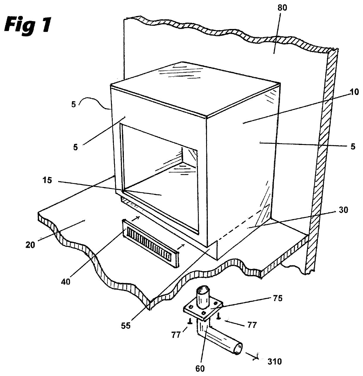
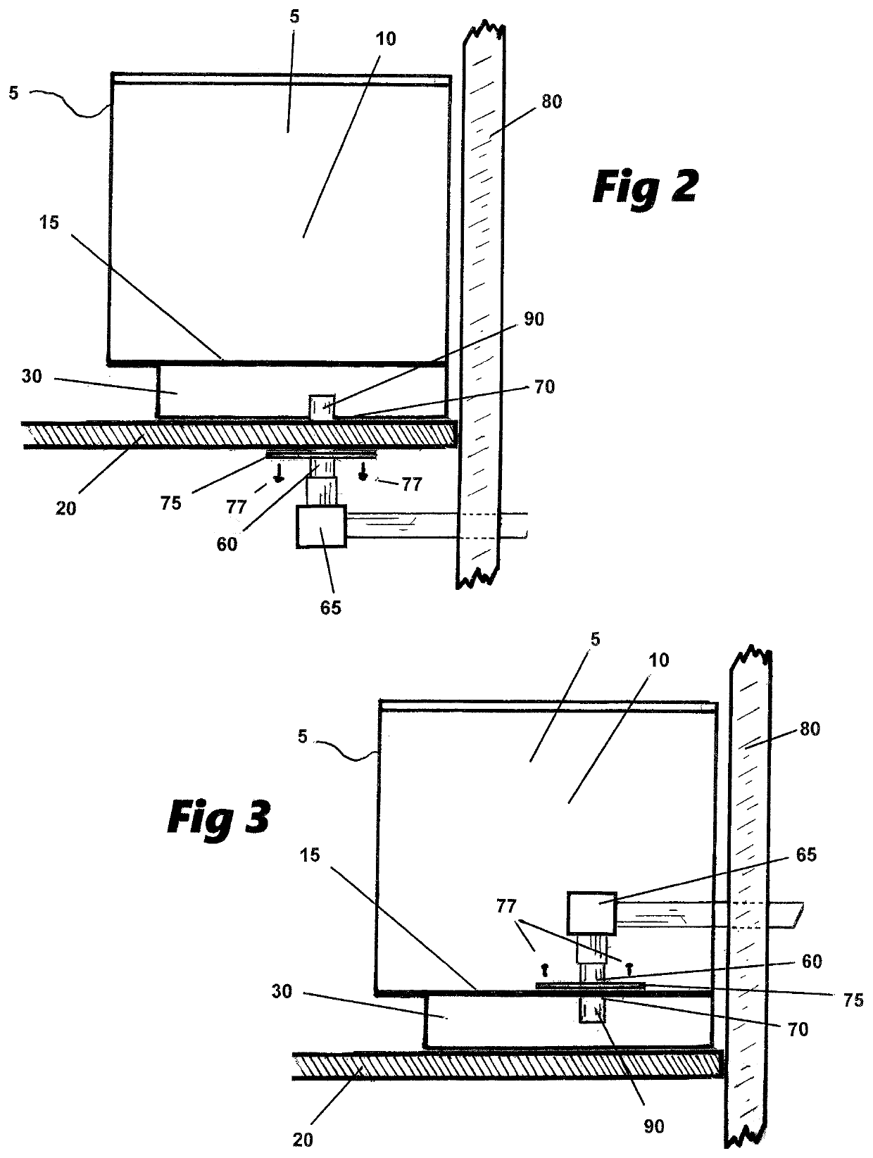
[0029]As shown in perspective view in FIG. 1 and in side view in FIGS. 2, 3 & 8, the ventilation system is normally installed in a cabinet (10) typically found in a kitchen or bath of a contemporary home. Kitchen & bath cabinets (10) feature a lower shelf (15) which is designed to heighten the usable lower surface of the cabinet a distance above the actual floor (20) of the buil...


PUM


Abstract

A ventilation system comprising a plenum below the lower shelf of a cabinet combined with ductwork and special fan applications designed to evacuate air from the interior to the exterior of a building. The system is designed to eliminate issues normally encountered when retrofitting a ventilation system into an existing building.

Description

CROSS REFERENCE TO RELATED APPLICATIONS[0001]This application claims the benefit of Provisional Patent Application 62 / 603,514, Filing date Jun. 5, 2017 Confirmation No. 9475.FIELD OF THE INVENTION[0002]The invention relates to ventilation systems such as those typically installed in kitchens and bathrooms which are designed to exhaust air from inside a building to the outside through an opening in a wall or roof of the building. Due to the installation requirements, these types of ventilation systems are typically included when the building is being constructed. Retrofit installations require a considerable amount of reconstruction in order to create the required opening, install the fan and switches and bring electric service to the unit. The present invention is designed to eliminate many of these installation problems.[0003]Typical ventilation systems include a housing positioned within a building structure, such as an aperture in a wall or ceiling. The housing is generally secur...

Claims


Application Information

Patent Timeline
Patent Type & Authority Applications(United States)
IPC IPC(8): F24F13/02F24F7/10F24F13/06
CPCF24F7/10F24F13/0209F24F13/0254F24F13/0604F24F2007/001F24F13/0227
Inventor HANUS, JOHN P.
Owner JOHN P HANUS
Why Eureka
Try Eureka