Mechanical prosthetic heart valve

a heart valve and mechanical technology, applied in the field of mechanical prosthetic heart valves, can solve the problems of inconvenient replacement, inconvenient placement of upper bearing means on the internal peripheral surface of the annular support, limited life of tissue valves,

Active Publication Date: 2021-07-15
NOVOSTIA SA
View PDF6 Cites 1 Cited by
  • Summary
  • Abstract
  • Description
  • Claims
  • Application Information

AI Technical Summary

Problems solved by technology

However, these tissue valves have a limited life because they unavoidably become calcified over time, which means that they need to be replaced after ten years or so on average.
The shape and location of the upper bearing means on the internal peripheral surface of the annular support are not, however, optimal because these means are in contact with the leaflet only in the vicinity of the leading edge.
As a result, the loadings applied to the leaflet in this region at the start of opening and at the end of opening are concentrated on areas with a small radius of curvature both on the leaflet and on the supports, leading to very high contact pressures and therefore to significant wear.
This configuration leads to high forces of reaction between the guide means, something which encourages premature wear particularly at the level of that zone of the leaflets that slides along the circular part of the extensions.
It has also been found that, with the impact of leaflet closure, the upper bearing means experience significant loadings to prevent the leaflet from continuing to move beyond the closed position.
With a small contact area, significant wear is found to occur in this region.

Method used


Image

  • Mechanical prosthetic heart valve
  • Mechanical prosthetic heart valve
  • Mechanical prosthetic heart valve

Examples


Embodiment Construction

OF EMBODIMENT OF THE INVENTION

[0063]In describing the illustrative, non-limiting embodiments illustrated in the drawings, specific terminology will be resorted to for the sake of clarity. However, the disclosure is not intended to be limited to the specific terms so selected, and it is to be understood that each specific term includes all technical equivalents that operate in similar manner to accomplish a similar purpose. Several embodiments are described for illustrative purposes, it being understood that the description and claims are not limited to the illustrated embodiments and other embodiments not specifically shown in the drawings may also be within the scope of this disclosure.

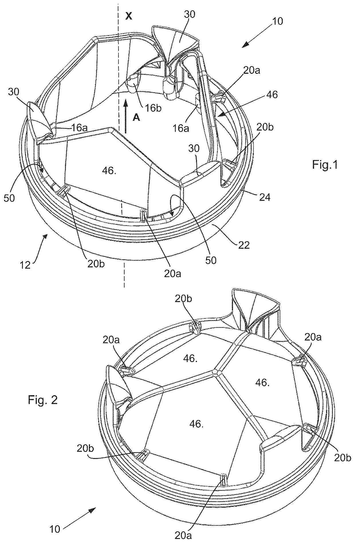
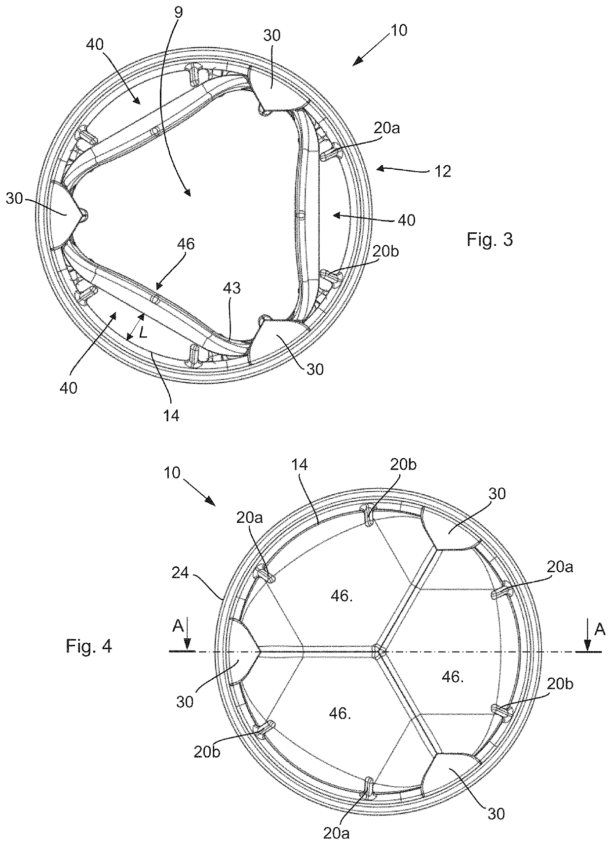
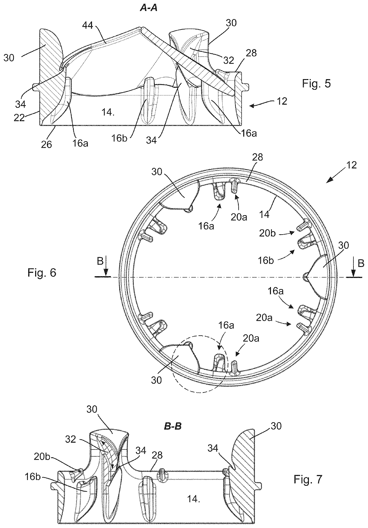
[0064]As illustrated notably in FIGS. 1 to 4, a mechanical prosthetic heart valve 10 comprises a ring-shaped annular support 12 which within it defines a central internal passage 9 (also see FIG. 6) for the cyclic flow of blood under the action of the contractions of the heart. The flow passing throu...


PUM


Abstract

The invention relates to a mechanical prosthetic heart valve (10) comprising: an annular support (12) having an internal peripheral wall (14) centered about a longitudinal axis (X) and delimiting an internal passage, and at least two mobile leaflets, preferably three mobile leaflets (40), arranged in such a way as to each be able to effect a rotational movement about an axis of rotation perpendicular to said longitudinal axis (X) so that the valve (10) can pass from a closed configuration to an open configuration and vice versa. Each leaflet (40) comprises a leading edge (42) designed to come against a portion of the internal peripheral wall (14) of the annular support (12) when the valve is in a closed configuration, an internal surface (46b) extending from the leading edge (42), and an external surface (46a) opposite the internal surface (46b) and extending from the leading edge (42). The annular support (12) comprises, on the internal peripheral wall (14), at least one lower bearing member (16a, 16b) per leaflet situated between two of said extensions (30) and designed to be in contact against the corresponding leaflet when the valve (10) is in the closed configuration, and two upper bearing members (20a, 20b). The two upper bearing members (20a, 20b) comprise each a distal end (21). Each distal end (21) is designed to come to bear against a bearing zone of the external surface (46a) of the leaflet (40). The center of the bearing zone is set back from the leading edge (42) of the leaflet (40) by a distance greater than a thickness of said leaflet at the center of said bearing zone.

Description

RELATED APPLICATION[0001]The present application claims priority to Swiss Application No. CH 00043 / 20, filed Jan. 14, 2020, the entire contents of which are hereby incorporated by reference.TECHNICAL FIELD[0002]The present invention relates to a mechanical prosthetic heart valve.PRIOR ART[0003]A distinction is made between two broad families of prosthetic heart valves. One of these families covers valve prostheses made of flexible tissue arranged on rigid struts in order to mimic the natural valves, referred to as tissue valves. The other of these families covers mechanical valve prostheses which are devices with no relationship to the shape of a natural valve and which are manufactured from wear-resistant and biologically compatible artificial materials.[0004]Because of their anatomical configuration and physiological mode of operation, tissue valves offer biological performance aspects similar to those of a natural heart valve because they conform to the natural structure of the f...

Claims


Application Information

Patent Timeline
Patent Type & Authority Applications(United States)
IPC IPC(8): A61F2/24
CPCA61F2/2424A61F2230/0023A61F2/2403
Inventor PERRIER, PHILIPPE
Owner NOVOSTIA SA
Why Eureka
Try Eureka