Hidden fastener unit and related method of use

Pending Publication Date: 2021-09-09
NAT NAIL
View PDF0 Cites 1 Cited by
  • Summary
  • Abstract
  • Description
  • Claims
  • Application Information

AI Technical Summary

Benefits of technology

[0018]The current embodiments of the fastener unit and related methods of use provide benefits in hidden fasteners that previously have been unachievable. For example, where the fastener unit includes a multi-dimensioned fastener hole defined by the spacer body, the spacer body can be configured to hold a fastener therein, yet not split or become damaged when the fastener is advanced through the spacer body. Where the fastener includes one or more fracturable joints between the spacer body and one or more of the board engagement elements, those elements can be easily removed and discarded from the unit to fit a particular joist combination or confined space, or can become disassociated from the remainder of the fastener unit after performing a particular function, such as clamping or securing the fastener unit to a board. Where the unit includes the board engagement element, such as a resilient compression element, that element can secure and hold the fastener unit in place adjacent the groove, without the need for additional hands to hold the unit. This can enable a user to place multiple fastener units along a board groove, install another board adjacent those units, and then come back and secure all the fastener units so that the boards are held in a fixed manner relative to the underlying support structure. Where the grip

Problems solved by technology

The nails or screws can frequently become discolored over time, or can work themselves loose from the board and project upward from the board surface.
Not only are these results aesthetically displeasing, they can present safety hazards.
While the horizontal flanges can engage the grooves, these elements typically do not engage those grooves forcibly enough to tack the boards to the underlying joist and prevent them from moving during expansion and contraction under changing temperatures.
These systems typically also require a user to manually hold the plate in alignment with one or more grooves of the boards as the fastener is advanced, which can be cumbersome.

Method used


Image

  • Hidden fastener unit and related method of use
  • Hidden fastener unit and related method of use
  • Hidden fastener unit and related method of use

Examples


Example

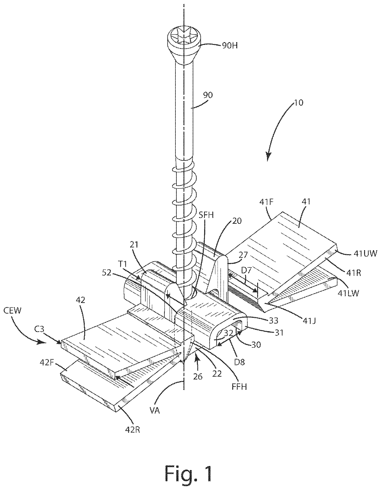
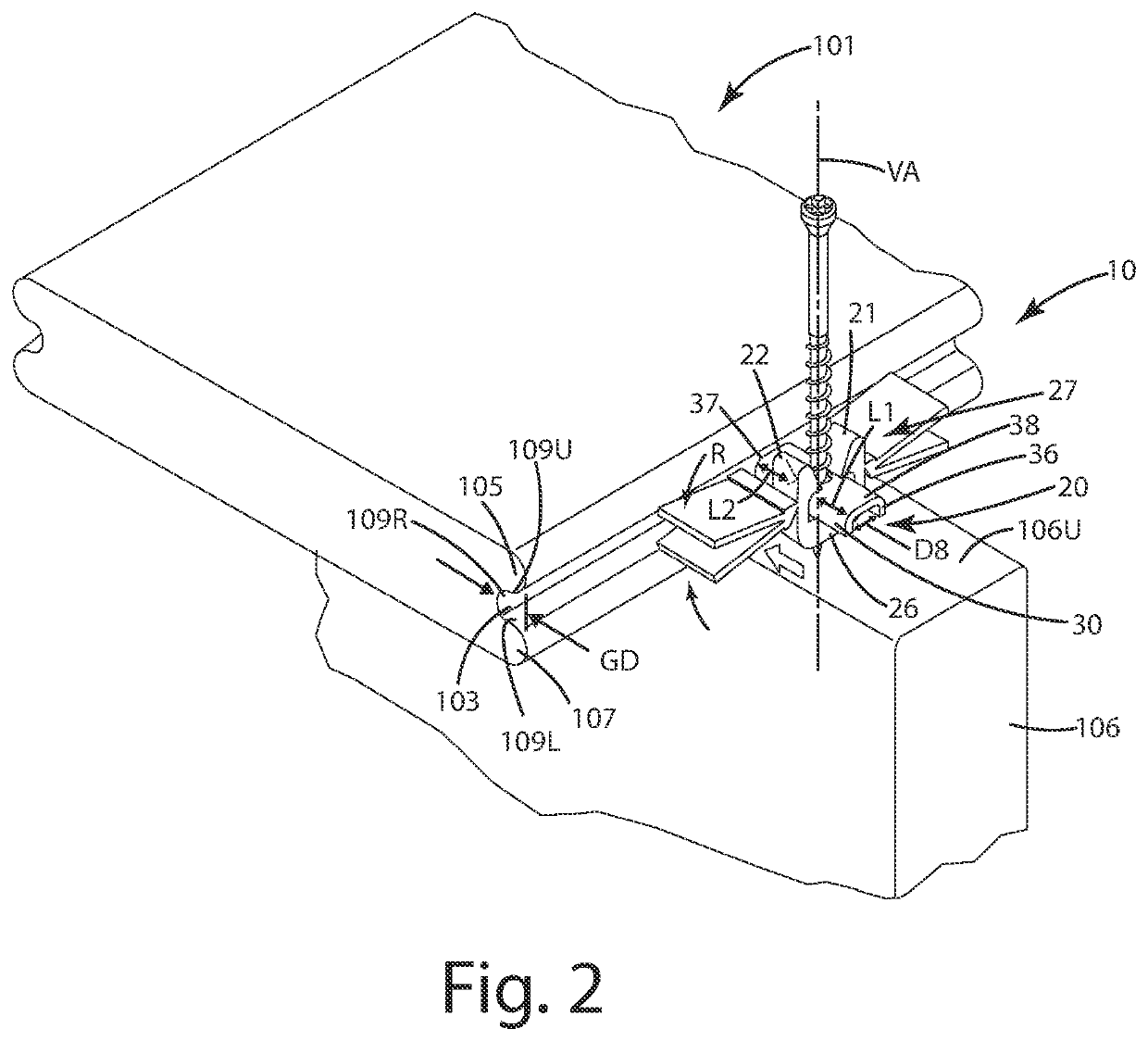
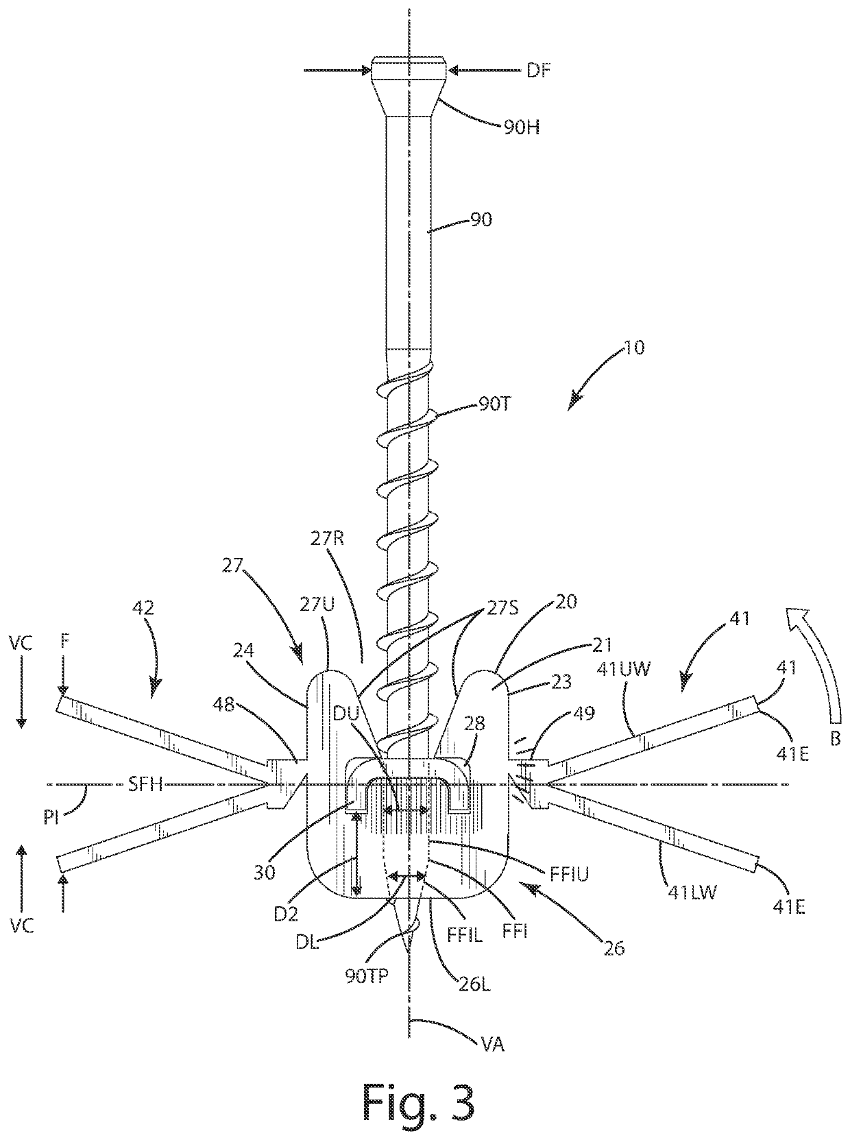
[0072]A current embodiment of the fastener unit is illustrated in FIGS. 1-7, and generally designated 10. The fastener unit 10 can generally include a spacer body 20, a grip element 30 protruding forwardly and rearwardly from the spacer block, also referred to as a spacer body herein, and one or more board engagement elements, such as a first resilient compression element 41 and a second resilient compression element 42. These compression elements can be joined with the spacer body optionally via respective fracturable joints 48 and 49. A fastener 90 can be at least partially disposed through the spacer body 20 and / or the grip element 30 when the unit is in an uninstalled state as shown in FIG. 1.

[0073]The current embodiments of the fastener unit 10 are well suited for a variety of building and construction projects, such as commercial, residential and other construction projects. The fastener units, however, can be modified for use in other applications, such as automotive, marine,...


PUM


Abstract

A fastener unit and related method for securing a board to a support is provided. The fastener unit includes a spacer block, a grip element extending from the spacer block and configured to fit in and engage a groove of the board, and one or more board engagement elements. The board engagement elements can engage the groove of the board, thereby securing the spacer block in a position adjacent the groove to establish a gap between the board and another board. Related methods of use also are provided.

Description

CROSS REFERENCE TO RELATED APPLICATIONS[0001]This application is a continuation-in-part of and claims priority to U.S. patent application Ser. No. 16 / 689,625, filed Nov. 11, 2019, entitled HIDDEN FASTENER UNIT AND METHOD OF USE, which is a continuation-in-part of U.S. patent application Ser. No. 16 / 537,128, filed Aug. 9, 2019, entitled HIDDEN FASTENER UNIT AND METHOD OF USE, which is a continuation-in-part of U.S. patent application Ser. No. 16 / 011,213, now U.S. Pat. No. 10,378,218 issued Aug. 13, 2019, entitled HIDDEN FASTENER UNIT AND METHOD OF USE, which is a continuation-in-part of U.S. patent application Ser. No. 29 / 648,131, now U.S. Pat. No. D850,897 issued Jun. 11, 2019 entitled FASTENER POSITIONING DEVICE, and which is a continuation-in-part of U.S. patent application Ser. No. 29 / 649,771, now U.S. Pat. No. D853,829 issued Jul. 16, 2019, entitled FASTENER POSITIONING DEVICE, and which claims priority to U.S. Provisional Application Ser. No. 62 / 674,247, filed May 21, 2018, U.S...

Claims


Application Information

Patent Timeline
IPC IPC(8): E04F15/02
CPCE04F15/02044E04F13/0826E04F15/02022E04F2015/02094E04F2201/0523E04F15/02183F16B5/002F16B5/0088
Inventor VANDENBERG, ROGER A.SCHWARTZKOPF, TODD E.A.
Owner NAT NAIL
Why Eureka
Try Eureka