
Hidden fastener unit and related method of use

a fastener unit and hidden technology, applied in the field of fastener units, can solve the problems of affecting the use of users, presenting safety hazards, and affecting the use of nails or screws, and achieve the effect of being easily perceived by users

Pending Publication Date: 2021-12-30
NAT NAIL
View PDF0 Cites 5 Cited by
  • Summary
  • Abstract
  • Description
  • Claims
  • Application Information

AI Technical Summary

Benefits of technology

The fastener unit described in this patent allows for secure and easy installation of joists and other building materials. The unit includes a resilient compression element that can be compressed to fit into a groove and then expanded to secure the unit to the board. The fastener can be easily removed and replaced with different joist combinations or space limitations. The grip element prevents the board from moving or creeping during expansion and contraction. The spacer body is thin and can be well concealed between boards. The board engagement element can be disassociated from the spacer body and used to temporarily hold the unit in different locations and orientations. The resilient compression element works at different angles and can fit into various groove heights. Overall, the fastener unit provides better and more efficient results for building construction.

Problems solved by technology

The nails or screws can frequently become discolored over time, or can work themselves loose from the board and project upward from the board surface.
Not only are these results aesthetically displeasing, they can present safety hazards.
While the horizontal flanges can engage the grooves, these elements typically do not engage those grooves forcibly enough to tack the boards to the underlying joist and prevent them from moving during expansion and contraction under changing temperatures.
These systems typically also require a user to manually hold the plate in alignment with one or more grooves of the boards as the fastener is advanced, which can be cumbersome.
Depending on the height of the base and the distance of the groove from the board lower surface, sometimes these items can be mismatched so that the flanges do not fit well in or align with the grooves.
In addition, the flanges are of a fixed thickness so that if that thickness is mismatched relative to a groove, the plate cannot fit in the groove, let alone secure the board to the underlying joist.
Further, where a support structure includes a double or triple joist, with two or more joists positioned immediately adjacent one another, the foregoing fastener systems might not be properly sized to conceal those joists or fit within the associated confined spaces.

Method used


Image

  • Hidden fastener unit and related method of use
  • Hidden fastener unit and related method of use
  • Hidden fastener unit and related method of use

Examples


fourth embodiment

[0190]As shown in FIGS. 17-20, the fastener unit 410 can include one or more board engagement element 440. As illustrated in this fourth embodiment, the board engagement element 440 can extend above the spacer block 420. This board engagement element 440 can be configured to engage an upper surface 105 of a first board 101 to cooperatively clamp with the grip element 430, the spacer unit 410 adjacent the side surface 101S of the board 101. This board engagement element 440 can include first and second legs 441 and 442 that can extend downward to spacer block. The legs can contact, engage or be joined with and / or integral with the spacer block 420. The board engagement element 440 can also include a first platform 443 and / or an engagement arm 444 to sometimes referred to as a resilient arm or engagement arm herein.

[0191]With reference to FIGS. 17-20, the first and second legs can be joined to the upper portions 420U of the spacer block 420. Each of the legs can include an upper end 4...

fifth embodiment

[0212]In the fifth embodiment, the board engagement element 540 and its components can engage the spacer block 520 to set a distance between the board engagement element 540 and the grip element 530. In turn, this can set the fastener unit 510. The fastener unit 510 as shown can be a two piece unit, with the board engagement element separable and independently constructed from the spacer body, in a clamped mode or an expanded mode. For example, the engagement of the legs 541 and the track 522L shown in FIG. 25 can set a preselected distance between the arm 544, and in particular its lowermost portion 544N, and the grip upper surface 530U of the grip element 530. By adjusting the legs, and sliding them within the respective tracks, the distance D2 can be altered to another distance, for example D21, which can be a lesser distance, when the fastener unit 510 is in a clamping mode shown in FIG. 28 relative to an extended mode shown in FIG. 25. In general, the first and second legs are ...

tenth embodiment

[0275]An eleventh alternative embodiment of the fastener unit is illustrated in FIGS. 68-72 and generally designated 1110. The fastener unit of this embodiment is similar in structure, function and operation to the embodiments described above with several exceptions. For example, this unit 1110 can include a fastener 1190 similar to the fasteners described above. It also can include a grip element 1130 that is disposed in an aperture or recess 1128 defined by a spacer block 1120, similar to the embodiments described above. The grip element 1130 optionally can extend from and beyond the front and rear surfaces 1121, 1122 of the spacer block 1120. The spacer block 1120 can be configured to establish a gap between adjacent boards, and sized with a thickness T12 similar to the thicknesses T1-T11 above. The unit 1110 can include first and second resilient compression elements 1141, 1142 joined with the spacer block 1120, the compression elements having fixed and moveable wings 1141F, 114...


PUM


Abstract

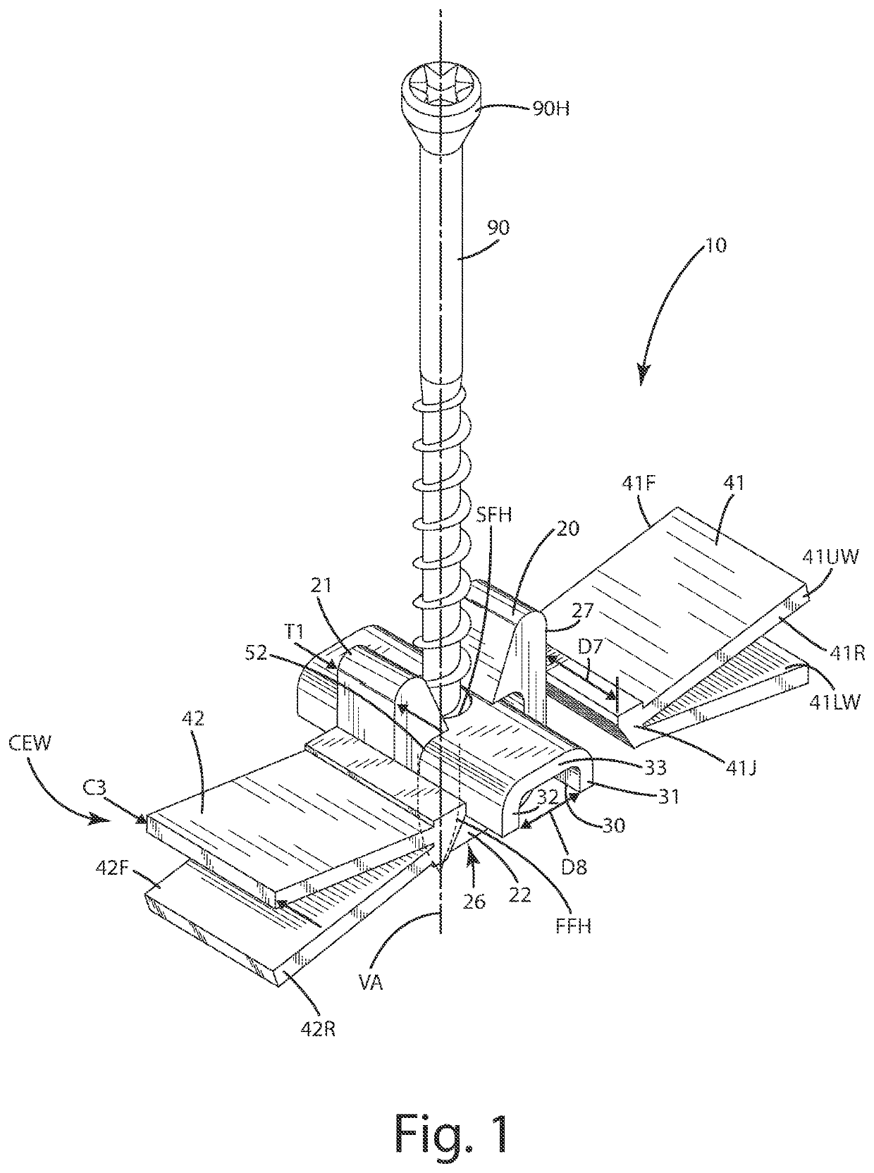
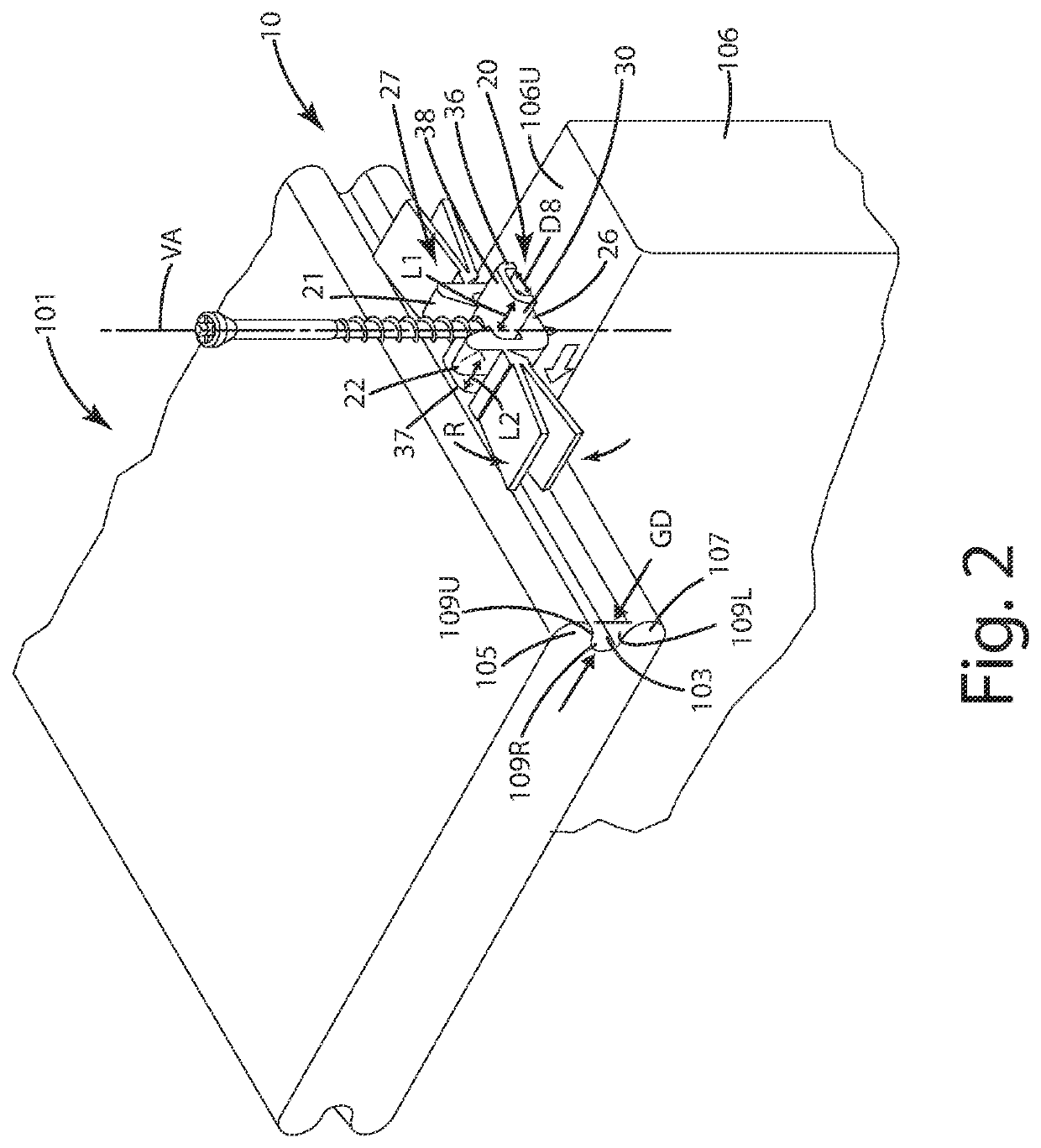
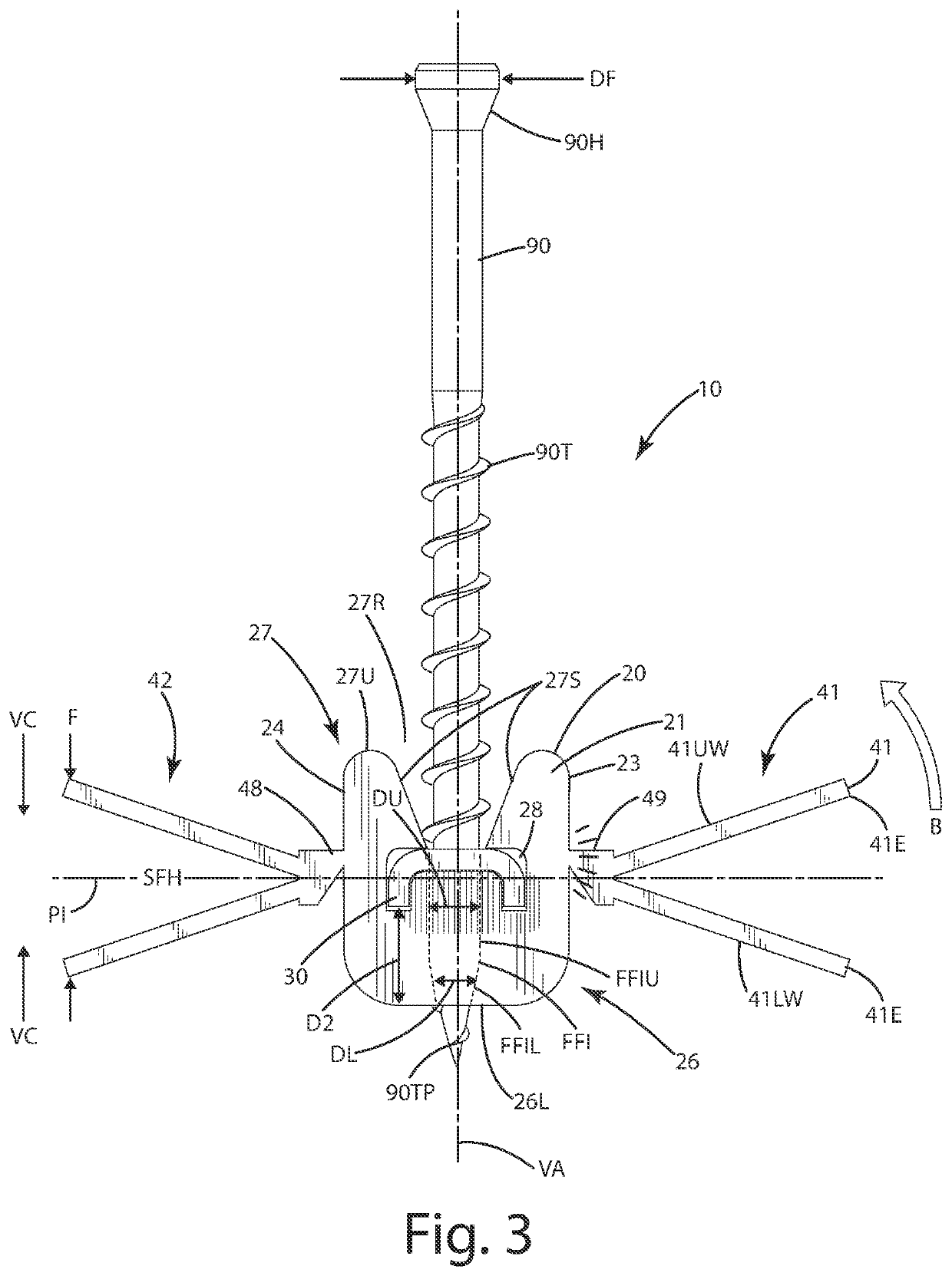
A fastener unit and related method for securing a board to a support is provided. The fastener unit includes a spacer block, a grip element extending from the spacer block and configured to fit in and engage a groove of the board, and one or more resilient compression elements joined with the spacer block. The resilient compression elements can be vertically compressible so at least a portion of it can move from an open mode to a compression mode and fit within, then forcibly expand within, the groove, thereby securing the spacer block in a position adjacent the groove to establish a gap between the board and another board. Related methods of use also are provided.

Description

BACKGROUND OF THE INVENTION[0001]The present invention relates to a fastener unit configured to fasten workpieces, such as boards, to support structures, such as joists, and more particularly to a fastener unit that engages a groove in the side of a board to secure the board to a support structure.[0002]There are a variety of structures, such as decks, platforms and flooring, that include horizontal floors supported by an underlying support structure. The structures typically include boards that are placed side-by-side one another. The boards typically are arranged to extend cross support structures, such as joists, disposed under the boards at an angle, sometimes at a right angle. The boards usually are fastened to the joists using fasteners, such as nails or screws. The nails or screws can frequently become discolored over time, or can work themselves loose from the board and project upward from the board surface. Not only are these results aesthetically displeasing, they can pres...

Claims


Application Information

Patent Timeline
Patent Type & Authority Applications(United States)
IPC IPC(8): E04F15/02E04F13/08F16B5/06F16B5/00E04F15/18
CPCE04F15/02044E04F13/0801F16B5/0621E04F2015/02094E04F15/183E04F2201/0523F16B5/002E04F21/1877E04F15/02022
Inventor VANDENBERG, ROGER A.SCHWARTZKOPF, TODD E.A.
Owner NAT NAIL
Learn More