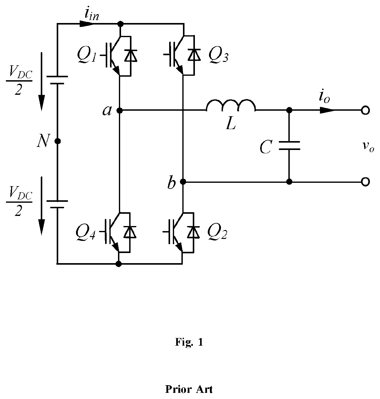
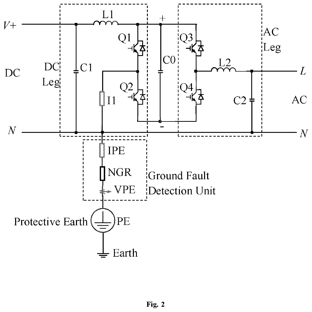
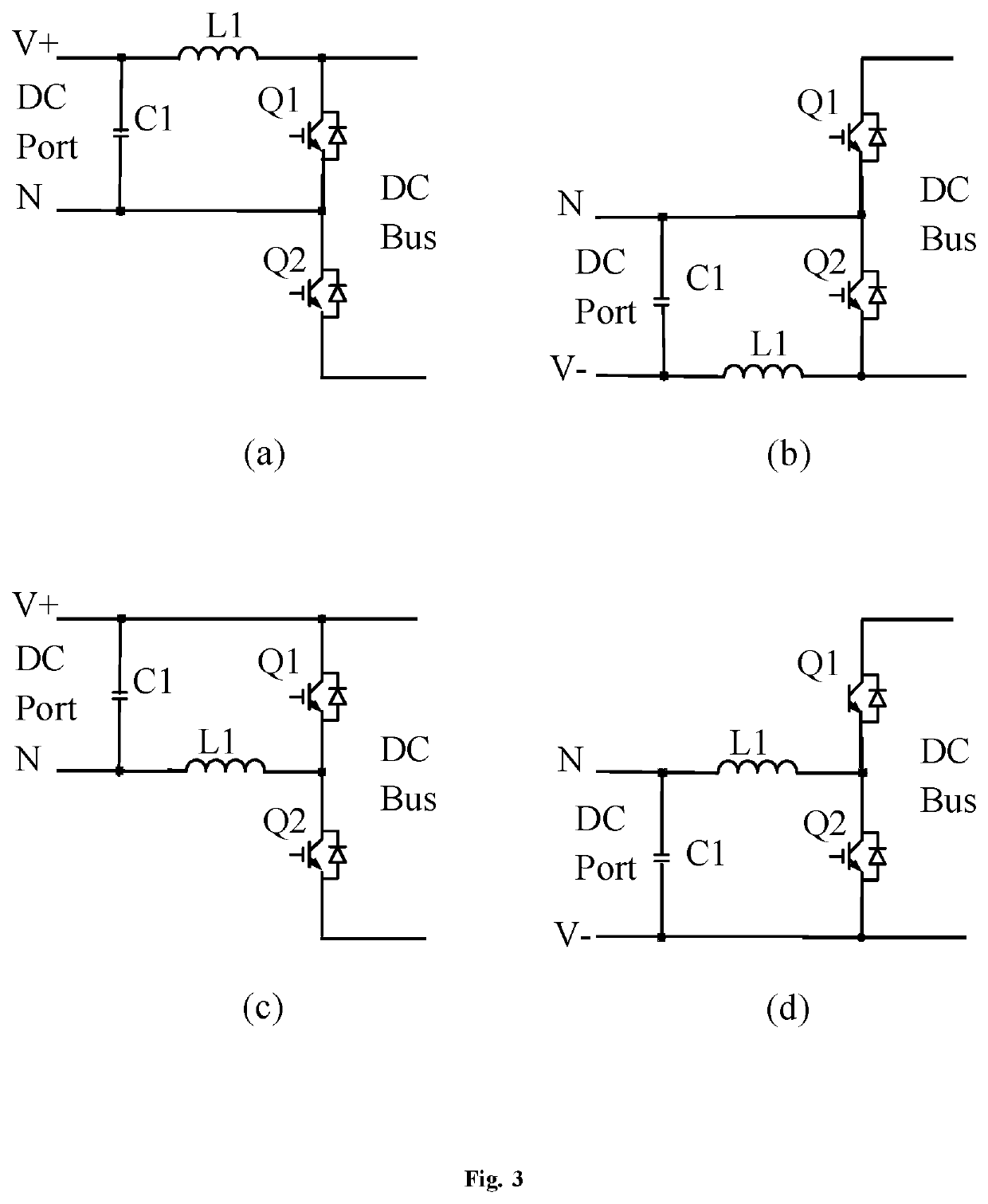
Power Electronic Converter with a Ground Fault Detection Unit that Shares a Common Ground with both DC Ports and AC Ports

Pending Publication Date: 2022-01-13
ZHONG QINGCHANG
View PDF17 Cites 1 Cited by
  • Summary
  • Abstract
  • Description
  • Claims
  • Application Information

AI Technical Summary

Benefits of technology

The invention is a power converter that can quickly detect, monitor, and protect against ground faults. This helps to improve the efficiency and reliability of the converter.

Problems solved by technology

Due to the rapid growth of global economy, the demand for electricity is constantly increasing, leading to energy crisis and environmental issues.
This presents great challenges to the safety of equipment and personnel, in particular, when ground faults occur.
A ground fault is an unintentional contact between an energized conductor and ground or equipment frame.
Because of insulation breakdown and other reasons, ground faults happen frequently.
However, without proper protection in place, it could lead to large currents, arcing, fire, electrical shock, equipment damage, or even fatalities.

Method used


Image

  • Power Electronic Converter with a Ground Fault Detection Unit that Shares a Common Ground with both DC Ports and AC Ports
  • Power Electronic Converter with a Ground Fault Detection Unit that Shares a Common Ground with both DC Ports and AC Ports
  • Power Electronic Converter with a Ground Fault Detection Unit that Shares a Common Ground with both DC Ports and AC Ports

Examples


Embodiment Construction

[0017]The particular values and configurations discussed in these non-limiting examples can be varied and are cited merely to illustrate at least one embodiment and are not intended to limit the scope thereof.

[0018]The embodiments will now be described more fully hereinafter with reference to the accompanying drawings, in which illustrative embodiments of the invention are shown. The embodiments disclosed herein can be embodied in many different forms and should not be construed as limited to the embodiments set forth herein: rather, these embodiments are provided so that this disclosure will be thorough and complete, and will fully convey the scope of the invention to those skilled in the art.

[0019]The terminology used herein is for the purpose of describing particular embodiments only and is not intended to be limiting of the invention. As used herein, the singular forms “a,”“an.” and “the” are intended to include the plural forms as well, unless the context clearly indicates othe...


PUM


Abstract

This invention discloses a power electronic converter that streamlines the detection, monitoring, and protection of ground faults. The converter has at least one DC leg with each having a DC port and a first DC bus, at least one AC leg with each having an AC port and a second DC bus, at least one DC-bus capacitor, a ground-fault detection unit, and a Protective Earth terminal that is connected to the earth. The DC port(s). AC port(s), and the ground-fault detection unit are connected together to share a commons ground, which is also the neutral line of the AC ports. The first DC bus(es) of the DC port(s) and the second DC bus(es) of the AC port(s) are connected together to form a converter DC bus with the DC-bus capacitor(s) connected to it. The ground-fault detection unit, connected between the common ground and the Protective Earth terminal, consists of a current sensor and a neutral ground resistor connected in series, together with a voltage sensor to measure the voltage between the Protective Earth terminal and the common ground. When the voltage of the Protective Earth terminal with respect to the common ground exceeds a certain value or when the current flowing through the ground-fault detection unit exceeds a certain value, a visual or audio warning signal is generated to warn the presence of a ground fault. A Residual Current Circuit Breaker or a Ground Fault Circuit Breaker can be connected to the AC port(s) to disconnect the converter in case of ground faults. Possible applications include any field that adopts power electronic converters that converts electricity between DC and AC, e.g., in wind power, solar power, storage systems, home appliances, IT equipment, motor drives, electric vehicles, more-electric aircraft, and all-electric ships.

Description

CROSS-REFERENCE TO RELATED APPLICATIONS[0001]This nonprovisional patent application claims the benefit of and priority under 35 U.S. Code 119 (b) to U.K. Patent Application No. GB2010378.4 filed on Jul. 7, 2020, entitled “Power Electronic Converter with a Ground Fault Detection Unit that Shares a Common Ground with both DC Ports and AC Ports”, the contents of which are all hereby incorporated by reference herein in its entirety.TECHNICAL FIELD[0002]This invention discloses a power electronic converter that streamlines the detection, monitoring, and protection of ground faults. Possible applications include any field that adopts power electronic converters to convert electricity between DC and AC, e.g., in wind power, solar power, storage systems, home appliances, IT equipment, motor drives, electric vehicles, more-electric aircraft, and all-electric ships.BACKGROUND[0003]Due to the rapid growth of global economy, the demand for electricity is constantly increasing, leading to energy...

Claims


Application Information

Patent Timeline
IPC IPC(8): H02H7/122H02M1/00G01R31/52
CPCH02H7/122G01R31/52H02M1/0009H02M3/158H02M1/32H02M7/53871G01R31/42H02M1/123H02M1/0095H02H3/16Y02E10/76H02H7/10H02M1/10H02M7/00H02H7/1203H02H3/04H02H1/0038
InventorZHONG, QINGCHANG
OwnerZHONG QINGCHANG