
Scan chain fail diagnostics

Inactive Publication Date: 2010-07-15
MENTOR GRAPHICS CORP
View PDF21 Cites 6 Cited by
  • Summary
  • Abstract
  • Description
  • Claims
  • Application Information

AI Technical Summary

Benefits of technology

[0008]The following summary is provided to facilitate an understanding of some of the innovative features unique to the embodiments disclosed and is not intended to be a full description. A full appreciation of the various aspects of the embodiments can be gained by taking into consideration the entire specification, claims, drawings, and abstract as a whole.
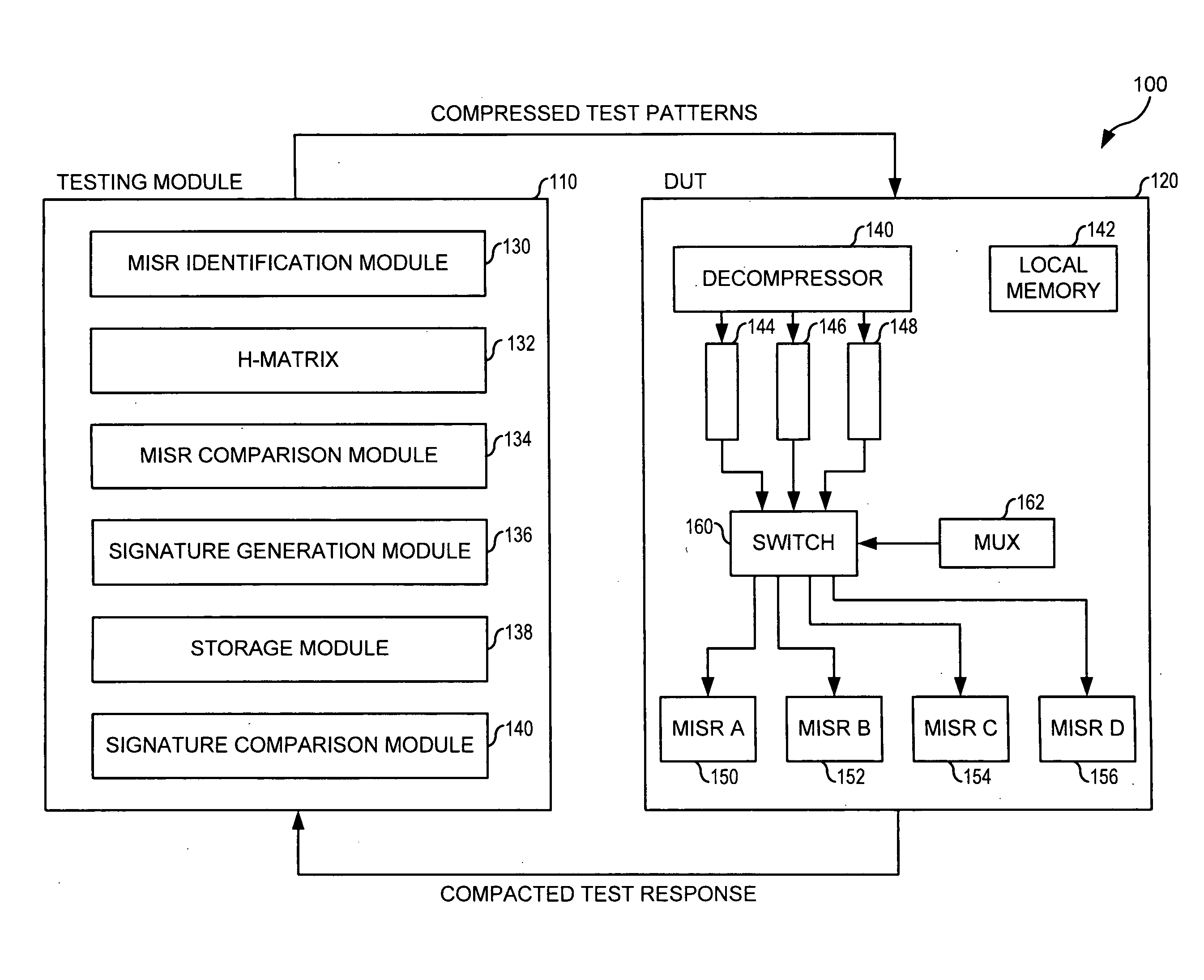
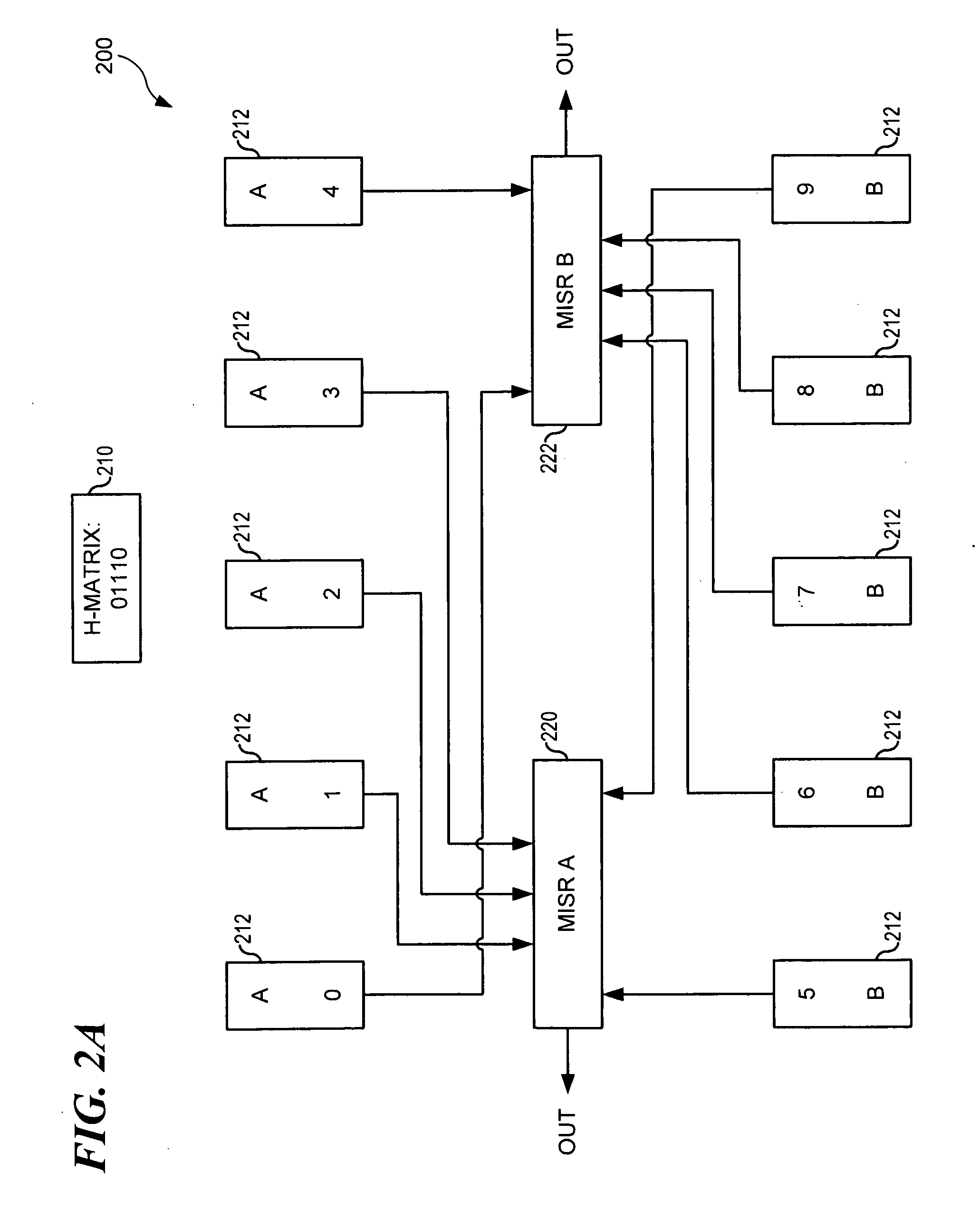
[0009]A method comprises generating a test pattern for a device under test (DUT), wherein the DUT comprises a plurality of scan chains coupled to a plurality of multiple input shift registers (MISRs). The plurality of faults detected by a first MISR and by a second MISR are identified. In the event the plurality of faults detected by the first MISR does not include any of the plurality of faults detected by the second MISR and the plurality of faults detected by the second MISR does not include any of the plurality of faults detected by the first MISR, the first MISR and the second MISR are coupled as an independent MISR pair. The test pattern is applied to the DUT to generate a scan chain output. The independent MISR pair captures the scan chain output to generate a test signature. The test signature is c

Problems solved by technology

Though the signature effectively reduces the total output data down to the width of the MISR (usually between 10 and 40 bits from 100,000×50,000), diagnosing fails within the system becomes significantly more difficult and time consuming as compaction increases.
In the event that the resultant signature is incorrect, common test systems must execute a complicated series of additional tests to identify the failing scan chain, frequently requiring multiple runs of the exact same test pattern.

Method used


Image

  • Scan chain fail diagnostics
  • Scan chain fail diagnostics
  • Scan chain fail diagnostics

Examples


Embodiment Construction

[0017]The particular values and configurations discussed in these non-limiting examples can be varied and are cited merely to illustrate at least one embodiment and are not intended to limit the scope of the invention.

[0018]In the following discussion, numerous specific details are set forth to provide a thorough understanding of the present invention. Those skilled in the art will appreciate that the present invention may be practiced without such specific details. In other instances, well-known elements have been illustrated in schematic or block diagram form in order not to obscure the present invention in unnecessary detail. Additionally, for the most part, details concerning network communications, electro-magnetic signaling techniques, user interface or input / output techniques, and the like, have been omitted inasmuch as such details are not considered necessary to obtain a complete understanding of the present invention, and are considered to be within the understanding of pe...


PUM


Abstract

A method comprises generating a test pattern for a device under test (DUT), wherein the DUT comprises a plurality of scan chains coupled to a plurality of multiple input shift registers (MISRs). The plurality of faults detected by a first MISR and by a second MISR are identified. In the event the plurality of faults detected by the first MISR does not include any of the plurality of faults detected by the second MISR and the plurality of faults detected by the second MISR does not include any of the plurality of faults detected by the first MISR, the first MISR and the second MISR are coupled as an independent MISR pair. The test pattern is applied to the DUT to generate a scan chain output. The independent MISR pair captures the scan chain output to generate a test signature. The test signature is compared with a known good signature.

Description

CROSS-REFERENCE TO RELATED APPLICATIONS[0001]This application relates to co-pending U.S. patent application entitled IMPROVED TEST PATTERN COMPRESSION (Docket No. AUS920080369US1), filed concurrently herewith.TECHNICAL FIELD[0002]The present invention relates generally to the field of circuit testing and, more particularly, to a system and method for improved scan chain fail diagnostics.BACKGROUND OF THE INVENTION[0003]Modern circuit design incorporates methods and hardware that enable circuit testing upon completion of production, often referred to as “design for test” or “design for testability” (DFT). One DFT technique utilizes scan chains. In a scan chain system, certain latches, independent of their assigned cone of logic, couple together into a hardware connection known as a “scan chain.” The test system inputs a test pattern into the scan chain latches, which the system then uses to test the functionality of the circuit. As such, scan chains allow for increased testability an...

Claims


Application Information

Patent Timeline
IPC IPC(8): G01R31/3177G06F11/25
CPCG01R31/318566G01R31/318547
Inventor WARD, SAMUEL I.CROSBY, PATRICK R.RAMSOUR, WILLIAM D.TRUONG, BAO G.
Owner MENTOR GRAPHICS CORP
Learn More