
Eureka
For R&D, Eureka makes reading and utilizing patents & technical documents easy.
Eureka AIR
Designed for self-driven R&D workflows. Generate viable solutions, solve complex R&D challenges, empower your innovation with AI.

Eureka Materials
Designed for material experts only. Revolutionize your material R&D, from search, analyze, to developing new materials.

TechResearch
Generate reliable direction feasibility study reports for your R&D in just a few steps.

TechSeek
Discover and master advanced knowledge NOW. Basics, ideas, possibilities, all at once.

TechMind
As an expert in R&D Theories, TechMind can generates customized viable solutions instantly.

TechRisk
Analyze your overall solution with one click, know your potential R&D risks in advance.

TechMonitor
Get weekly tech updates, stay abreast of the latest tech innovations and key insights.
Printing apparatus
- Summary
- Abstract
- Description
- Claims
- Application Information
AI Technical Summary
Benefits of technology
Problems solved by technology
Method used
Image

Examples
first embodiment
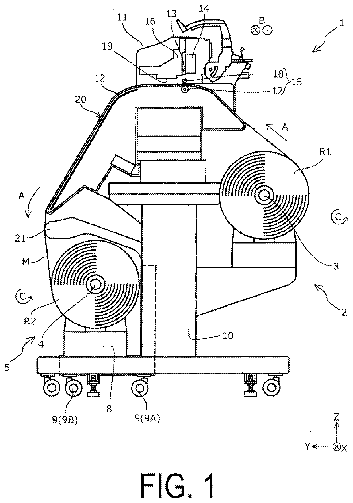
[0028]Hereinafter, an embodiment according to the present disclosure will be described in detail with reference to drawings. First, a printing apparatus 1 according to a first embodiment of the present disclosure is described with reference to FIG. 1. Here, in FIG. 1, some constitutional members are omitted for facilitating the understanding of the configuration. Here, in the drawing, an X-axis direction is a horizontal direction, and corresponds to a winding axis direction B parallel to an extending direction of a holding member 3 on which a roll body R1 of a medium M to be subjected to printing is set, and an extending direction of a holding member 4 that is configured to wind the medium M subjected to the printing as a roll body R2. A Y-axis direction is a horizontal direction, and corresponds to a direction orthogonal to the X-axis direction. Further, a Z-axis direction is a vertical direction. Still further, in the description made hereinafter, an arrow direction is assumed as ...
second embodiment
[0059]Next, a printing apparatus 1 according to a second embodiment will be described with reference to FIG. 6. Here, FIG. 6 is a view corresponding to FIG. 4 illustrating the printing apparatus 1 of the first embodiment. In FIG. 6, the constituent members common to those in the first embodiment described above are denoted by the same reference numerals, and their detailed description will be omitted. Here, the printing apparatus 1 of the present embodiment has substantially the same configuration as the printing apparatus 1 of the first embodiment other than a configuration of a wheel 9 as a contact portion. Accordingly, the printing apparatus 1 of the present embodiment has substantially the same features as the printing apparatus 1 of the first embodiment with respect to a configuration other than a configuration described below.
[0060]As illustrated in FIG. 6, in the printing apparatus 1 of the present embodiment, a spring member S is provided to each wheel 9. Accordingly, also i...
PUM
 Abstract
Description
Claims
Application Information
 - R&D Engineer
- R&D Manager
- IP Professional
- Industry Leading Data Capabilities
- Powerful AI technology
- Patent DNA Extraction
Browse by: Latest US Patents, China's latest patents, Technical Efficacy Thesaurus, Application Domain, Technology Topic, Popular Technical Reports.
© 2024 PatSnap. All rights reserved.Legal|Privacy policy|Modern Slavery Act Transparency Statement|Sitemap|About US| Contact US: help@patsnap.com