Identification arrangement and method

a technology of identification arrangement and arrangement method, which is applied in the direction of electric generator control, maintenance/maintenance of primary cells, secondary cells, etc., can solve the problems of limiting the number of different types of batteries which it is possible to distinguish, leaking chemical substances or outputing the wrong voltage or being charged in a wrong way, and the absolute tolerance of the first and second resistors limiting the number of different types of batteries

Inactive Publication Date: 2000-08-29
OPTIS WIRELESS TECH LLC
View PDF23 Cites 15 Cited by
  • Summary
  • Abstract
  • Description
  • Claims
  • Application Information

AI Technical Summary

Problems solved by technology

Otherwise the battery might for instance leak chemical substances or output the wrong voltage or be charged in a wrong way.
One disadvantage with the method and apparatus described in U.S. Pat. No. 5,200,686 is that the absolute tolerance of the resistor with the resistance that is to be measured is limiting the number of different types of batteries which it is possible to distinguish.
One disadvantage with the circuit described in U.S. Pat. No. 5,489,834 is that the absolute tolerance of the first and second resistor is limiting the number of different types of batteries which it is possible to distinguish.
One disadvantage with the technique described in EP 642,202 is that both the resistor connected between the regulator and the specification-discriminating terminal and the monitor resistor connected between the terminal connected to the specification-discriminating terminal of the battery and

Method used


Image

  • Identification arrangement and method
  • Identification arrangement and method
  • Identification arrangement and method

Examples


Embodiment Construction

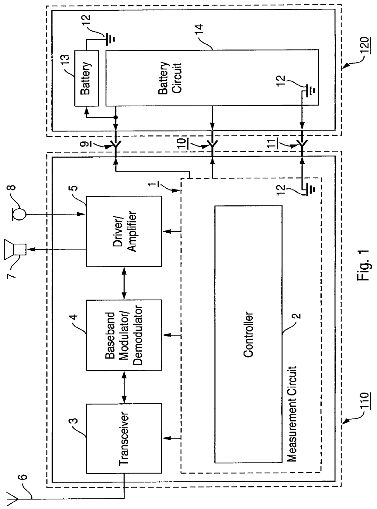
FIG. 1 illustrates a block view of an electronic equipment 110 and a battery equipment 120.

The electronic equipment 110 is a mobile station that comprises a measurement circuit 1 which comprises a controller 2. The controller 2 controls a transceiver 3, a baseband modulator / demodulator 4 and a driver / amplifier 5 of the mobile station 110. The transceiver 3 is coupled to an antenna 6 of the mobile station 110. The driver / amplifier 5 is coupled to a microphone 8 and a speaker 7 of the mobile station 110. The transceiver 3 and the baseband modulator / demodulator 4 are coupled to each other and also the baseband modulator / demodulator 4 and the driver / amplifier 5 are coupled to each other. The measurement circuit 1 is connected to a battery voltage connection 9, to a measurement and control connection 10 and to a ground connection 11 which is connected to ground 12. Hence, the measurement circuit 1 is connected to ground 12.

The battery equipment 120 comprises a battery 13 and a battery ci...


PUM


Abstract

The invention provides a battery identification arrangement, a battery equipment (120) suitable for identification and a battery identification method for implementation in an electronic equipment (110) such as a mobile station or a charger with a battery (13). The present invention also relates to a method to measure the temperature of a battery (13) connected to an electronic equipment (110). The battery identification arrangement includes both a measurement circuit (1) of the electronic equipment (110) and a battery circuit (14) of a battery equipment (120). On identifying, means in the measurement circuit (1) measure at least one identification voltage (Vid) which is generated by dividing a battery voltage (Vbat) into a division ratio by means of in series connected resistors (R1, R2) connected to ground (12). The resistors (R1, R2) are connected to the battery (13) only during measurement of the identification voltage (Vid) and the battery voltage (Vbat).

Description

The present invention relates to a battery identification arrangement of an electronic equipment with a battery and a battery equipment suitable for identification. The present invention also relates to a battery identification method for implementation in an electronic equipment with a battery. The present invention also relates to a method to measure the temperature of a battery connected to an electronic equipment.DESCRIPTION OF RELATED ARTSome portable radio communication equipments use a detachable rechargeable battery as a power supply.A portable radio communication equipment, which herein after is referred to as a mobile station, includes all portable radio communication equipment such as mobile stations, pagers, communicators, so called electronic organizers, or the like.Numerous different types of detachable battery types are available in view of the portability and power supply efficiency of the mobile station. A standard battery, i.e. a battery with a standard capacity, i...

Claims


Application Information

Patent Timeline
IPC IPC(8): H02J7/00H01M10/42H01M10/48H01M6/00H01M6/50
CPCH01M6/5066H01M10/425H01M10/48H02J7/0006H02J7/00038H02J7/00047Y02E60/10H02J7/00
Inventor OLSSON, JAN EVERT TORBJORN
Owner OPTIS WIRELESS TECH LLC
Why Eureka
Try Eureka