Method and apparatus for packet scheduling

a packet scheduling and packet technology, applied in the field of network communication systems, can solve the problems of inability to implement, inability to achieve, and inability to achieve practical solutions, so as to reduce congestion, reduce packet losses, and allocate bandwidth resources fair

Active Publication Date: 2010-01-12
MARVELL ASIA PTE LTD +1
View PDF14 Cites 11 Cited by
  • Summary
  • Abstract
  • Description
  • Claims
  • Application Information

AI Technical Summary

Benefits of technology

[0010]It is an object of the present invention to provide an improved packet scheduler, which achieves fair allocation of the bandwidth resources on the output link, reduces congestion and lowers packet losses. It is also an object of the present invention to provide a packet scheduler that has low complexity and is amenable to a simple hardware implementation.

Problems solved by technology

Network applications, such as video-conferencing and multimedia broadcasts, place large amounts of data on a network, thereby causing contention for network resources.
However, while GPS may provide an ideal method for best-effort and interactive connections in a theoretical sense, it is impossible to implement due to its requirement of infinitesimal sized packets.
It is not, therefore, a practical solution.
In general, although timestamp schedulers have good delay properties, they suffer from a sorting bottleneck that results in time complexities (i.e., work) of O(N) to O(log N), where N is the number of competing flows.
In addition, the implementation of timestamp schedulers requires a complicated data structure that typically is not well suited for hardware implementation.
Since all data of a flow to be transmitted in a round is transmitted at once, DRR has poor delay and burstiness properties, especially for flows with large weights.
SRR has short-term fairness and certain schedule delay bound, as well as O(1) time complexity.
In addition, SRR, like timestamp scheduling, is not simple to implement.
Plainly, the prior art scheduling techniques have significant drawbacks, and can often result in large queuing delays during busy periods.
Even with the large buffers provided in today's gateway products, queues can become congested.
During congestion periods, the buffers may become and remain close to full, subjecting packets to long delays, even when the intrinsic latency of a communications path is relatively small.
Even worse, packets might be dropped.

Method used


Image

  • Method and apparatus for packet scheduling
  • Method and apparatus for packet scheduling
  • Method and apparatus for packet scheduling

Examples


Embodiment Construction

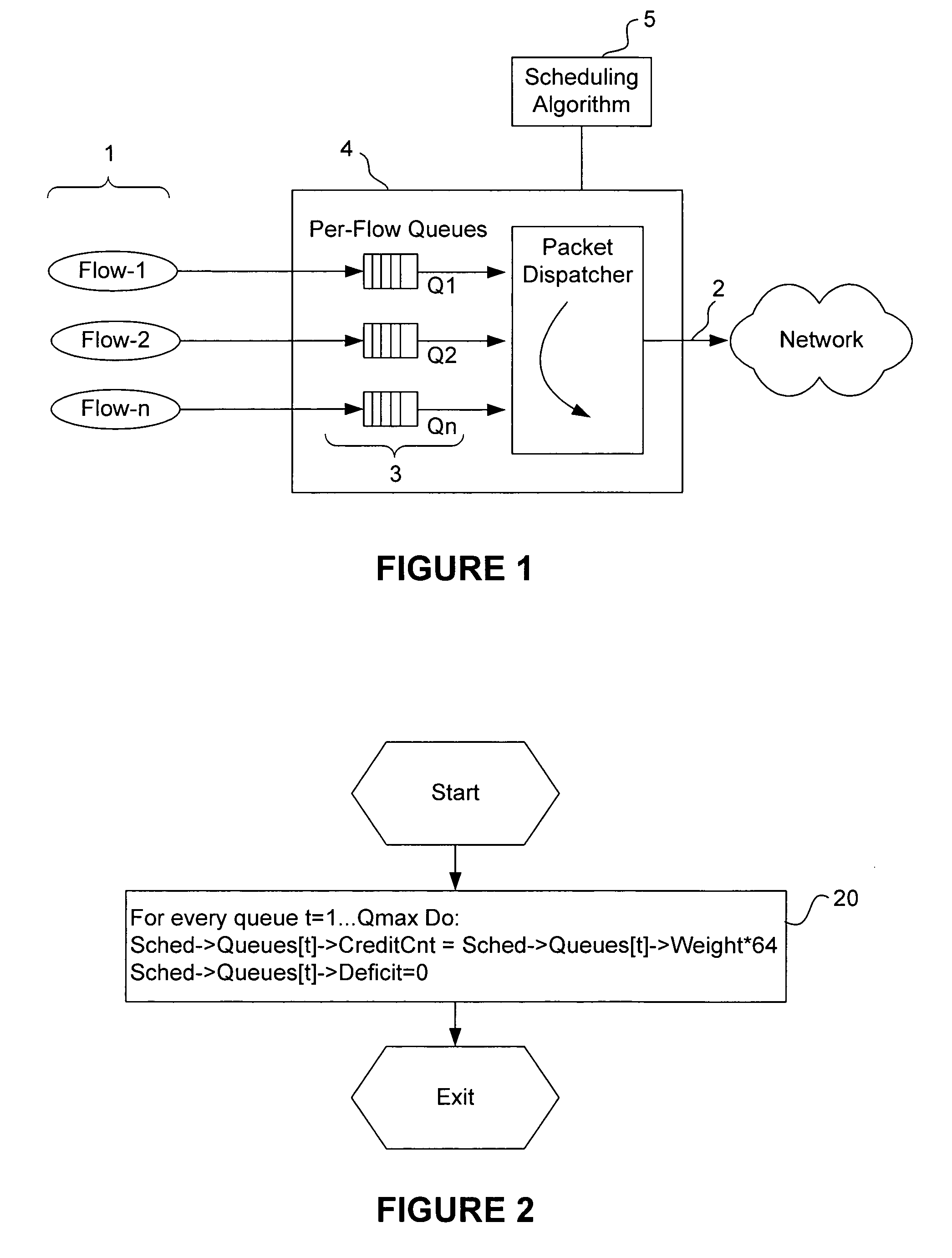
[0025]FIG. 1 illustrates a block diagram of a packet scheduler 4 in accordance with the present invention. The scheduling scenario considered here arises when a number of packet streams, called flows 1, share an output link at a switch. Each flow 1 maintains a separate queue 3 of its packets waiting for access to the transmission link 2. The packet scheduler 4 operates in accordance with a scheduling algorithm 5 to schedule the transmission of packets, so as to achieve a fair allocation of the bandwidth resources on the output link 2, reduce congestion and lower packet losses. The details of algorithm 5 are discussed in more detail below.

[0026]The packet scheduling algorithms can be realized in software recorded on a computer-readable storage medium. The invention could also be implemented on hardware, such as for example application specific integrated circuits (ASIC), programmable logic arrays (PLA), special purpose integrated circuits (ICs), digital signal processors (DSPs) or an...


PUM


Abstract

A methods, apparatus and computer memory are provided for packet scheduling. A processor polls queues in a round robin fashion and schedules for transmission onto a link a packet in each queue with no deficit before scheduling for transmission onto the link a packet in each queue with a deficit. A credit is allocated to each queue with the deficit based on a proportional weight, until each queue with the deficit has a credit.

Description

BACKGROUND OF THE INVENTION[0001]1. Field of the Invention[0002]The present invention relates to network communication systems, and in particular to packet scheduling.[0003]2. Description of the Related Art[0004]Network applications, such as video-conferencing and multimedia broadcasts, place large amounts of data on a network, thereby causing contention for network resources. Conventionally, such applications rely on packet scheduling algorithms in gateways to enhance performance and provide an acceptable level of quality of service. A packet scheduler controls the allocation of network interface bandwidth with respect to outgoing network flows, by deciding which packet is sent at a given time. In so doing, a packet scheduler determines how bandwidth is shared among flows and plays a key role in determining the rate and timing behavior of the transmission of data. A desirable and important property of a packet scheduler is the fairness it achieves in the allocation of the bandwidth...

Claims


Application Information

Patent Timeline
Patent Type & Authority Patents(United States)
IPC IPC(8): H01R31/08
CPCH04L12/5693H04L47/527H04L47/621H04L47/50
Inventor ANKER, TALDANIEL, TASAHI
Owner MARVELL ASIA PTE LTD
Why Eureka
Try Eureka