Cowling for outboard motor

a technology for outboard motors and cowlings, which is applied in the direction of marine propulsion, vessel construction, combustion air/fuel air treatment, etc., and can solve the problems of multiple pieces of protective cowlings, high manufacturing cost, and increased water splashing in the opening,

Inactive Publication Date: 2000-10-17
SANSHIN KOGYO CO LTD
View PDF32 Cites 30 Cited by
  • Summary
  • Abstract
  • Description
  • Claims
  • Application Information

AI Technical Summary

Problems solved by technology

The rearward facing air inlet opening, however, can cause a problem in that, when the watercraft is suddenly decelerated, water may splash up and enter the opening.
This is because baffling arrangements typically increase the airspeed of the intake air, which results in a greater tendency for water to remain suspended in the rushing air, rather than precipitate out of air flowing into the cowling.
In an addition, these complicated configurations are very expensive to manufacture and / or require multiple pieces for the protective cowling.
Certain portions of the engine are more prone to attack from corrosion and damage from the water than others.
For example, the ignition system including the spark plugs, spark coils and spark wires, can be seriously affected if water impinges upon them.
Misfiring can occur or in extreme situations the actual running of the engine can be interrupted.
In a similar manner, the charge forming system (e.g., a carburetor and / or throttle arrangement) can be subject to deterioration if water impinges upon it.
Of course, these problems are particularly aggravated if the engine is operated in a marine environment since the salt water will cause more corrosion than fresh water.
While it is possible to restrict the size of the openings in the protective cowling and thereby reduce the total amount of water traveling into the protective cowling, such restrictions would result in higher airspeeds of atmospheric air drawn into the restricted opening.
This consequently increases the amount of suspended water ingested by the engine as described above.
A restricted air passage can also significantly reduce engine performance, particularly under wide-open, full-throttle conditions.

Method used


Image

  • Cowling for outboard motor
  • Cowling for outboard motor
  • Cowling for outboard motor

Examples


Embodiment Construction

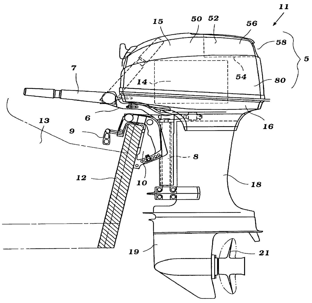
With reference now in detail to the drawings and initially to FIG. 1, an outboard motor constructed in accordance with an embodiment of the invention is identified generally by the reference numeral 11. The outboard motor 11 includes a power head, indicated generally by the reference numeral 5, which is comprised of an internal combustion engine 14 and a surrounding protective cowling. The protective cowling is comprised of an main cowling member 15 which is detachably connected to a lower cowling 16 with a sealing gasket (not shown) being interposed between these cowling components. The lower cowling 16, as is typical with this practice, is formed from a light weight, high strength material such as aluminum or aluminum alloy.

The main cowling member 15 is formed from a material which is also light weight such as a molded fiberglass reinforced resin. As will become apparent as the description proceeds, the main cowling member 15 is formed of a multi-part construction. Further details...


PUM


Abstract

A protective cowling arrangement provides atmospheric air to the engine of an outboard motor for engine cooling and combustion while inhibiting water intake. The protective cowling incorporates one or more air inlets, an air chamber, and ducts of different sizes for permitting atmospheric air to enter the engine compartment. One of these ducts, which is disposed in part above electrical components of the engine, is substantially shorter in length than the other duct. This duct thus has a smaller flow area without unduly restricting air flow through the duct. An air chamber cover is affixed to the engine and shields the ducts to afford further water preclusion.

Description

1. Field of the InventionThis invention relates to a cowling structure for a marine propulsion engine and, more particularly, to an improved cowling structure for permitting the induction of air for engine operation while inhibiting water from entering the engine compartment.2. Description of Related ArtA protective cowling of an outboard motor normally contains a powering internal combustion engine of the motor. The cowling insures that the engine and its auxiliaries do not become wet and subject to corrosion. At the same time, however, it is also necessary to provide atmospheric air to the engine for combustion and / or for cooling of the engine and its components. Because the engine requires substantial amounts of airflow for its combustion process, it is necessary to provide air openings in the protective cowling through which air may be drawn from the atmosphere. A wide variety of air induction systems have been proposed for outboard motors which serve the main purpose of providi...

Claims


Application Information

Patent Timeline
IPC IPC(8): F02B61/00F02B61/04F02M35/00F02M35/16F02B75/02B63H20/00F02B67/00F02B77/00
CPCF02B61/045F02M35/168F02M35/10013F02B2075/025
InventorNAKAYAMA, MANABUNOZAWA, TOMOHIRO
OwnerSANSHIN KOGYO CO LTD