Doup end tension regulating device for a selvedge former

a tension regulating device and selvedge former technology, which is applied in the direction of weaving, textiles, textiles and paper, etc., can solve the problems of increased wear of lifting healds, increased tension of spring assembly on the bobbin, and increased tension of thread on the bobbin

Inactive Publication Date: 2001-06-12
GEBR KLOCKER
View PDF12 Cites 9 Cited by
  • Summary
  • Abstract
  • Description
  • Claims
  • Application Information

AI Technical Summary

Benefits of technology

The invention provides a tool that can change how tight or loose different parts of a machine are connected together. This helps ensure that the size of the connection doesn't increase if other parts move around.

Problems solved by technology

The technical problem addressed in this patent is how to prevent the lengthening of thread when opening the shed while maintaining constant tension on the thread. Previous devices have used springs placed behind the lifting heals or held down by half heads, but these methods did not fully address the issue. The new invention provides a holding device that uses a spring elements to keep the thread under tension and ensure minimal loss of tension during use.

Method used


Image

  • Doup end tension regulating device for a selvedge former
  • Doup end tension regulating device for a selvedge former
  • Doup end tension regulating device for a selvedge former

Examples


Embodiment Construction

)

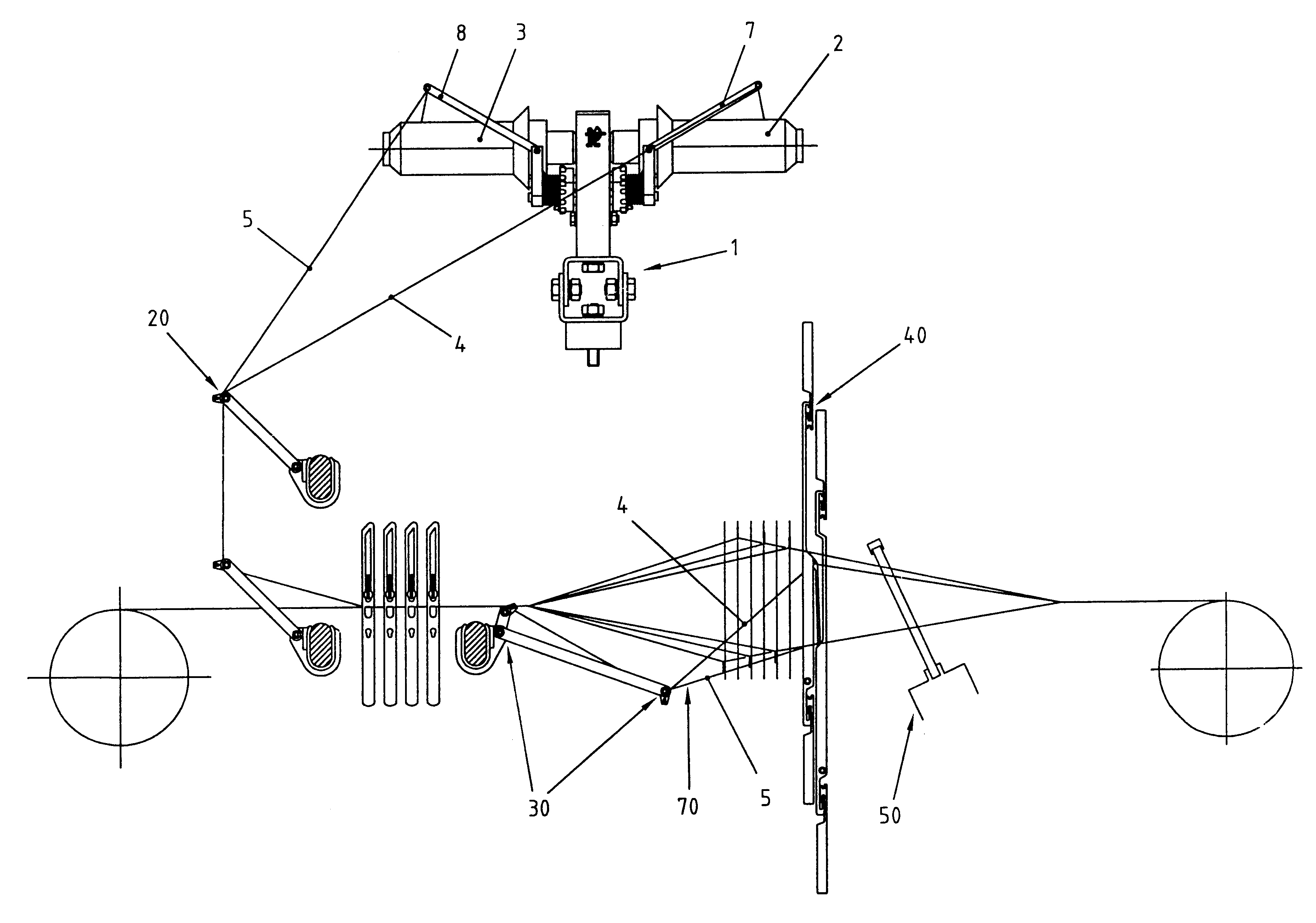
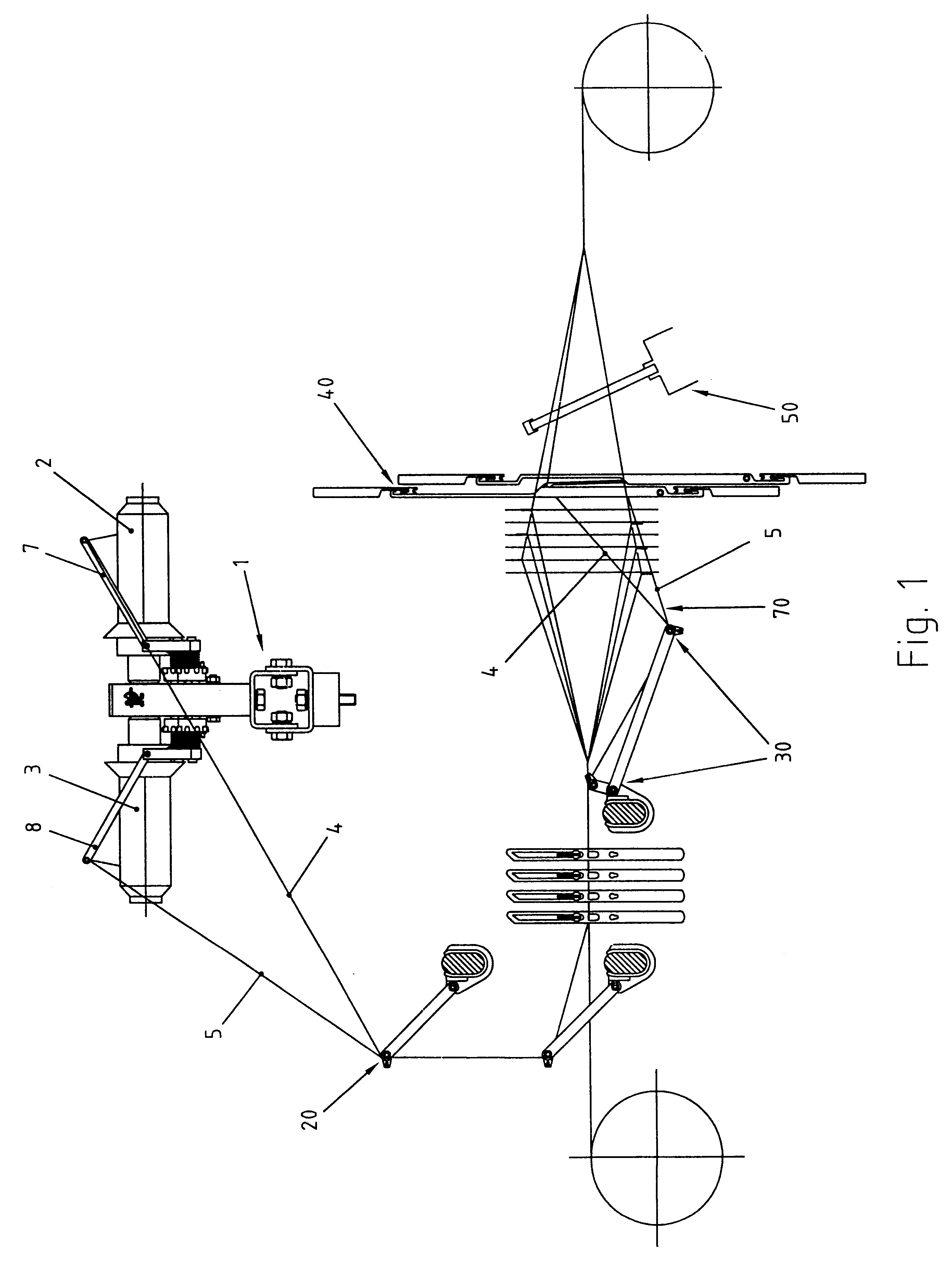
In FIG. 1, the overall bobbin carrier is referred to with numeral 1; the bobbin carrier 1 has the two bobbins 2 and 3 for receipt of the stationary thread or the doup end 4, 5 respectively. This bobbin carrier 1 is moreover provided with springy arms 7, 8 that serve to compensate diverging tensions in the threads 4, 5 while they are being unwound from the bobbins 2, 3.

The threads 4, 5 are deflected twice at the points 10, 20 before they reach the holding-down device for the thread 30 from which the threads are conveyed to the lifting healds 40. The reed, referred to as a whole with numeral 50, is connected behind the lifting healds 40. The function of the holding-down device 30 is to keep she threads 4, 5 under tension in the direction of the arrow 70.

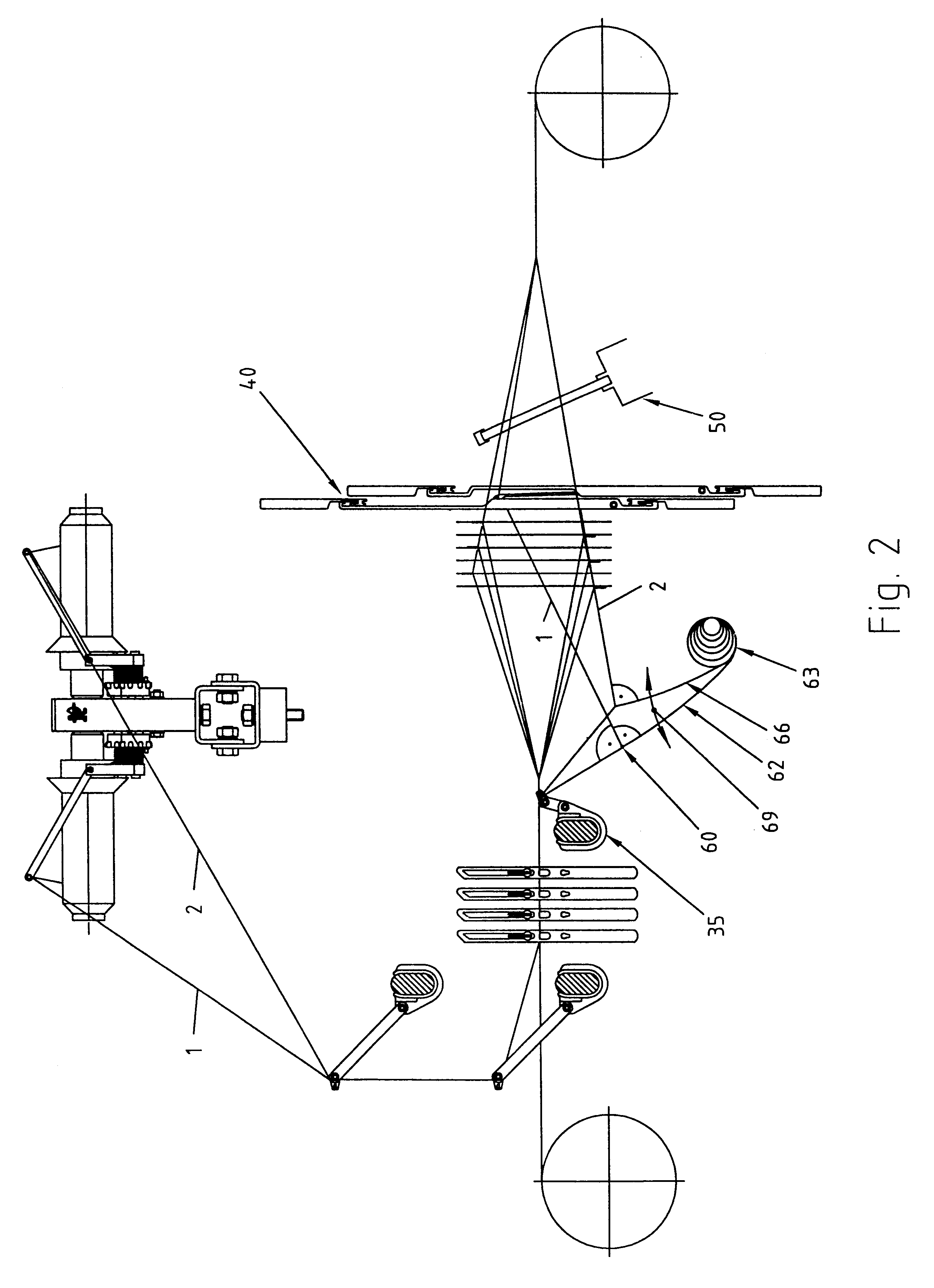
According to FIG. 2 a thread guide 35 remains instead of the holding-down device 30, the threads 4, 5 being however threaded through a holding device 63 at 60, whereas said holding device has two springy arms 62, 66, one for the doup ...


PUM


Abstract

In a leno selvedge device, an apparatus for adjusting thread tension of the doup ends and of the stationary threads that are guided through the leno selvedge forming device includes a holding structure accommodated directly in front of the leno selvedge device which keeps the stationary thread and/or the doup end under resilient tension. The holding structure includes at least one eyelet, through which thread is threaded. The eyelet is kept under tension by a spring and disposes the thread in a downward direction.

Description


Claims


Application Information

Patent Timeline
Owner GEBR KLOCKER
Why Eureka
Try Eureka