Work transfer method and apparatus in machine tool with movable spindle and machining system

a technology of machining system and machine tool, which is applied in the direction of turning machine accessories, metal working apparatus, manufacturing tools, etc., can solve the problems of enlargement of the machine tool as a whole, difficult to use in common the machine tool for machining work having a large diameter and the machine tool for machining a standard,

Inactive Publication Date: 2001-07-10
MORI SEIKI HITECH
View PDF7 Cites 20 Cited by
  • Summary
  • Abstract
  • Description
  • Claims
  • Application Information

AI Technical Summary

Problems solved by technology

In particular, in the case where the works having a large diameter are to be transferred, the work placement portions become large in physical size.
Thus, not only may an apparatus for transferring the work itself be enlarged but also it is necessary that the headstock be moved in the X-axis direction to perform the work receiving / sending operations, accordingly, this leads to an enlargement of the machine tool as a whole.
As a result, it is difficult to use in common the machine tool for machining the work having a large diameter and the machine tool for machining a standard size work.
Also, as a result of the enlargement of the work transfer apparatus and the operation of movement of the headstock, it tends to take long time for changing the works.

Method used


Image

  • Work transfer method and apparatus in machine tool with movable spindle and machining system
  • Work transfer method and apparatus in machine tool with movable spindle and machining system
  • Work transfer method and apparatus in machine tool with movable spindle and machining system

Examples


Embodiment Construction

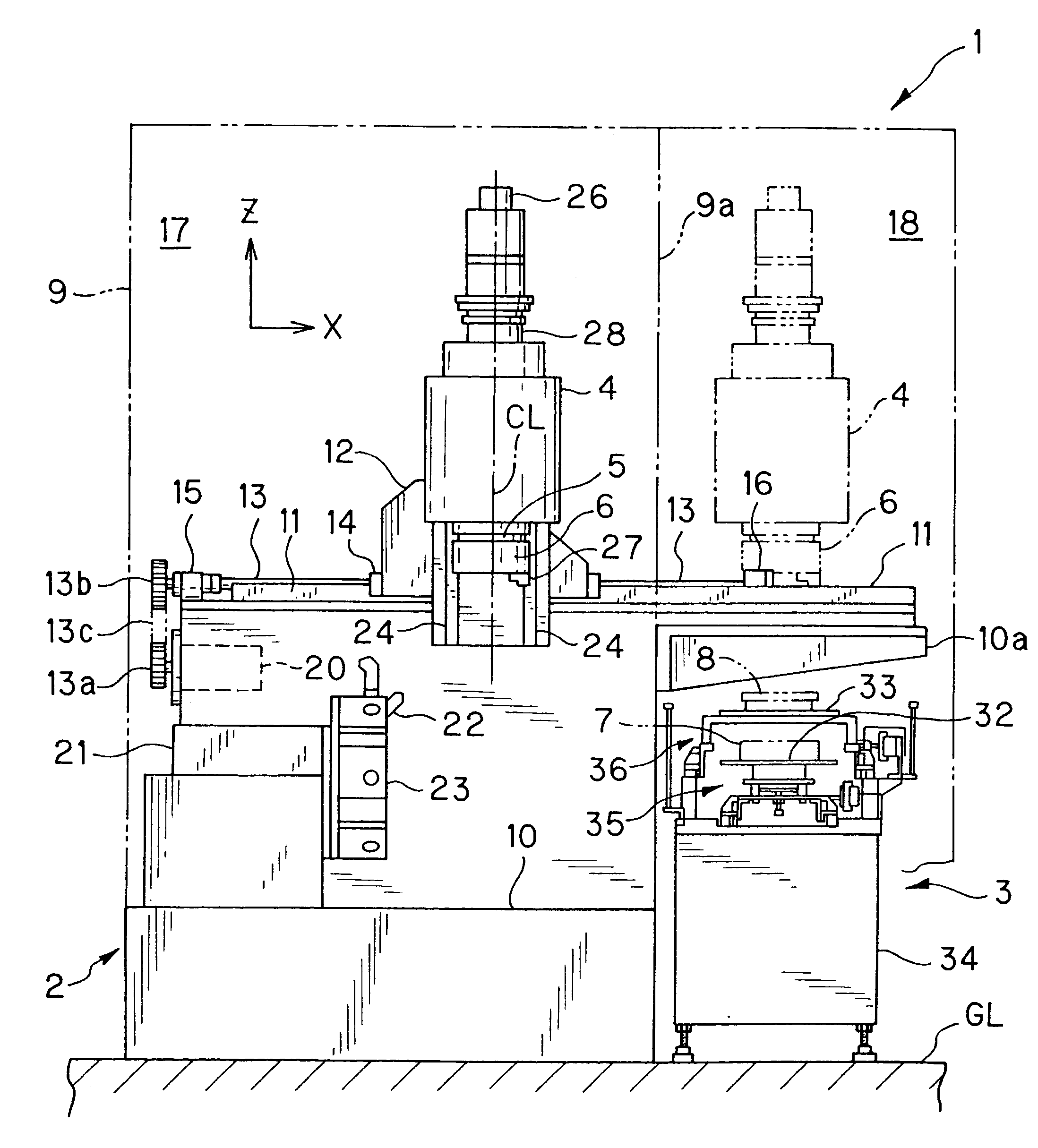
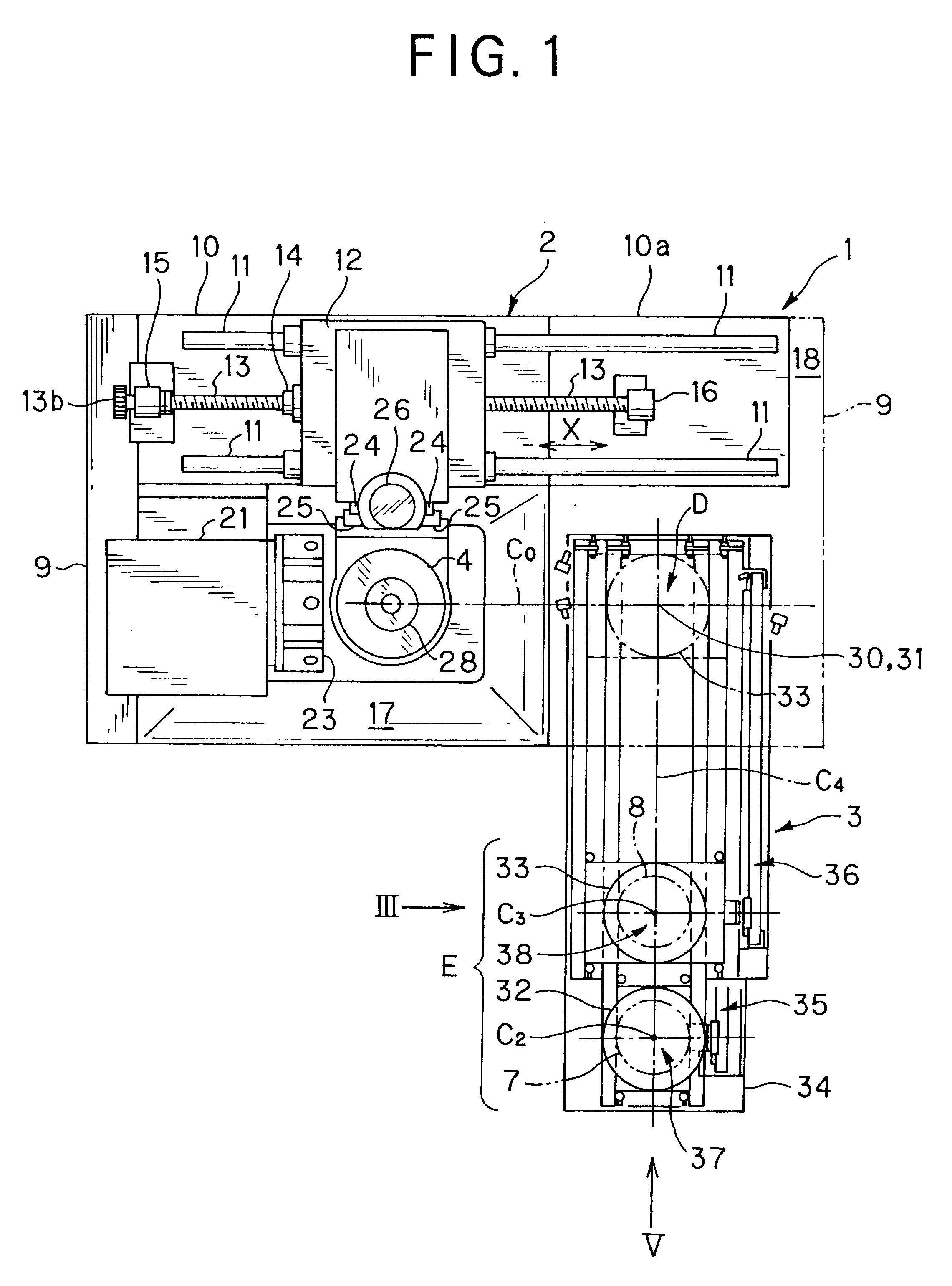
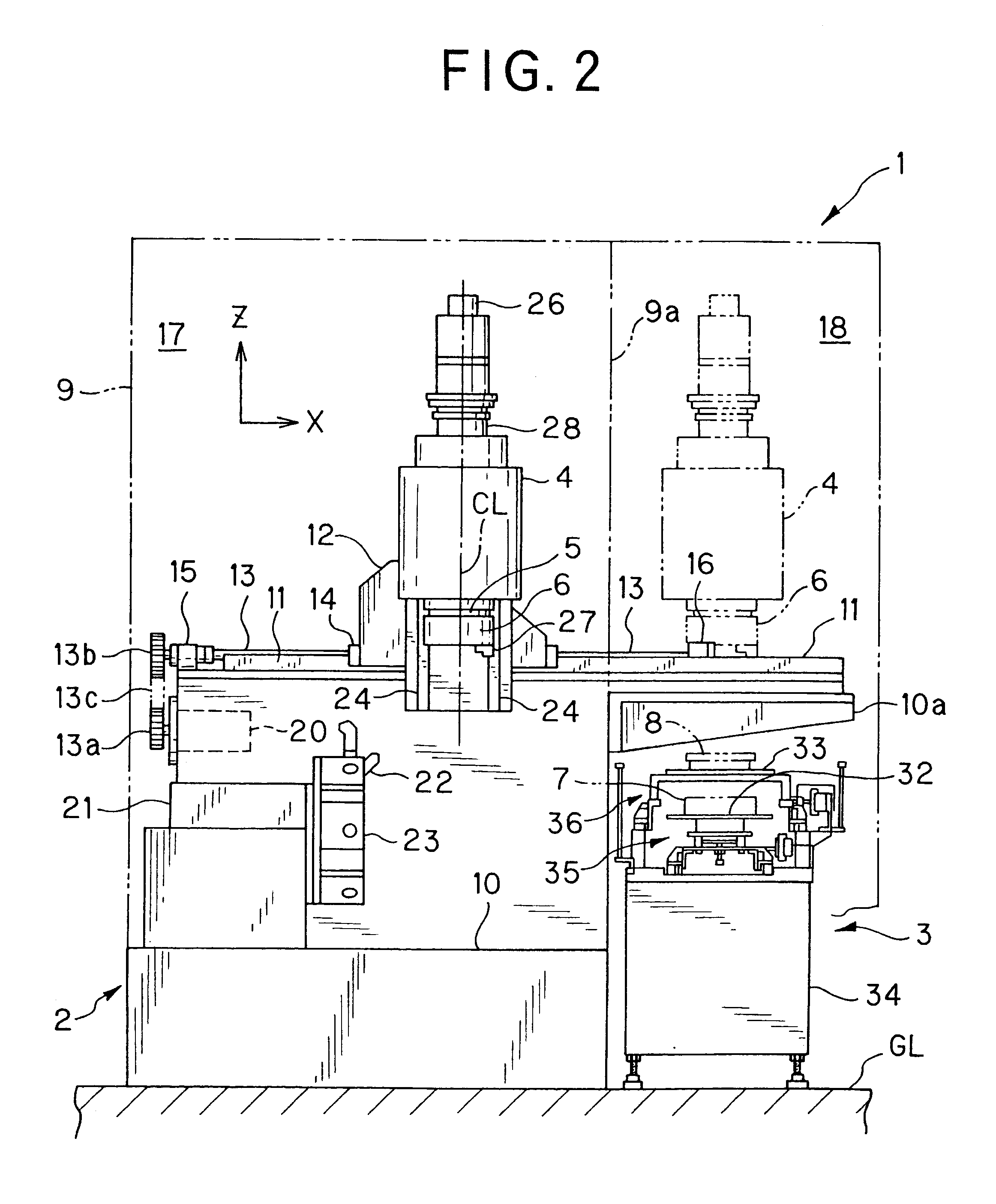
Embodiments of the present invention will now be described with reference to FIGS. 1 to 9.

In the embodiments, there is shown a vertical lathe as a machine tool with a movable main spindle to be numerically controlled by a numerical control (NC) device (not shown).

In this machine tool, a headstock for rotatably supporting the main spindle is moved at least in an axial direction of the spindle and in a direction perpendicular to the axial direction of the spindle to perform the operation of receiving / sending a work between a chuck provided at a lower end of the spindle and an apparatus for transferring the work. Also, the headstock may move between a work receiving / sending region and a machining region. If the machine tool is of this type, it is possible to apply the invention to any other machine tools such as a turning center, a grinding machine and a machining center. Namely, it is possible to apply the invention to the machine tool in which the headstock moves in three perpendicul...


PUM

PropertyMeasurementUnit
distanceaaaaaaaaaa
angleaaaaaaaaaa
diameteraaaaaaaaaa

Abstract

In a work transfer method in a machine tool with a movable spindle, a machined work transfer portion for laying a machined work on a first pallet and for transferring the work is disposed in an upper stage or a lower stage of a non-machined work transfer portion for laying a non-machined work on a second pallet and for transferring the work. Then, the non-machined work pallet is moved between a non-machined work receiving position and a work loading position. The machined work pallet is moved between a machined work sending position and a work unloading position. Thus, the work is received or sent between a chuck and a work transfer apparatus.

Description

1. Field of the InventionThe present invention relates to a work transfer method and a work transfer apparatus in a machine tool with a movable main spindle (i.e., movable spindle type machine tool) and a machining system therefor. In this machine tool, a headstock for rotatably supporting the spindle may move at least in an axial direction (Z-axis direction) of the spindle and in a direction (X-axis direction) perpendicular to the axial direction of the spindle. The work transfer apparatus serves to transfer a work (workpiece) in and out. The machine tool receives and sends the work between a chuck provided at a lower end of the spindle and the apparatus for transferring the work.2. Related ArtA work changer for changing works for the machine tool with the movable main spindle as related art (Japanese Patent Application No. 9-362060, i.e., Japanese Patent Application Laid-Open No. 11-170101) has been proposed. In this work changer, two or four portions for placing the works are for...

Claims


Application Information

Patent Timeline
Patent Type & Authority Patents(United States)
IPC IPC(8): B23Q7/00B23Q7/04B23B3/20B23B15/00B23Q39/04
CPCB23Q7/005B23Q7/047Y10T82/10Y10T82/2502Y10T82/2533Y10T82/2514
Inventor OTAKE, KIMITAKA
Owner MORI SEIKI HITECH
Why Eureka
Try Eureka