Driving device and lighting apparatus

a technology of driving device and lighting body, which is applied in the direction of lighting and heating apparatus, lighting support devices, fixed installation, etc., can solve the problems of affecting the operation of the lighting body, the coupling portion of the lighting body is difficult to prevent breakage, and the arm is damaged

Active Publication Date: 2017-10-26
MINEBEAMITSUMI INC
View PDF2 Cites 12 Cited by
  • Summary
  • Abstract
  • Description
  • Claims
  • Application Information

AI Technical Summary

Benefits of technology

[0005]An object of the present invention is to provide a driving device that is capable of preventing breakage while making it possible to change the orientation of an object of operation to an intended direction, and a lighting apparatus that is provided therewith.

Problems solved by technology

In the above-described conventional technology, however, it is difficult to prevent breakage while making it possible to change the orientation of an object of operation such as a light source to an intended direction.
For example, in the above-described lighting apparatus, because the lighting body is pivotally supported by the arm from the one lateral side, there may be a case that a coupling portion of the lighting body and the arm gets damaged due to the weight of the lighting body itself and the like.

Method used


Image

  • Driving device and lighting apparatus
  • Driving device and lighting apparatus
  • Driving device and lighting apparatus

Examples


embodiment

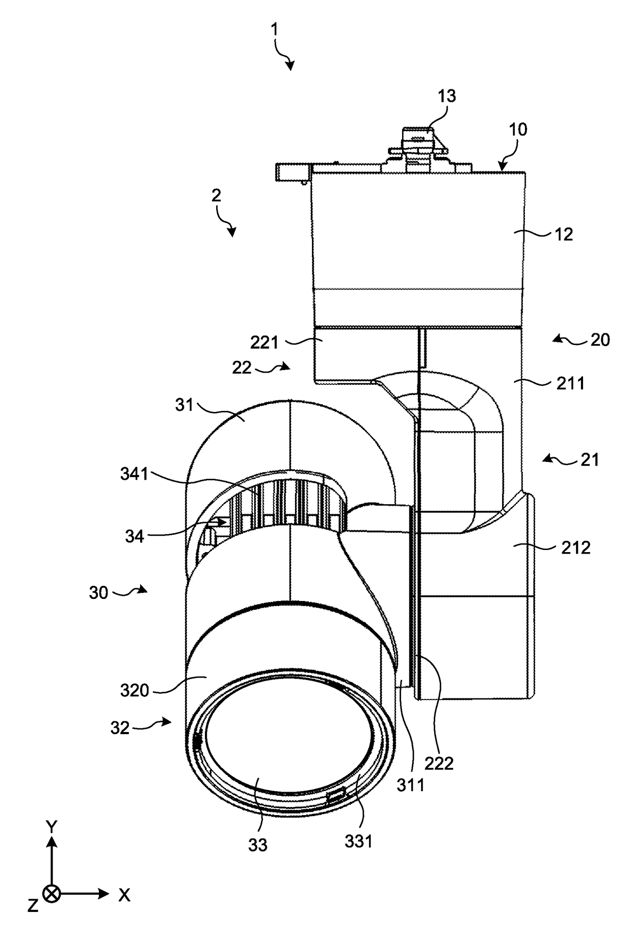
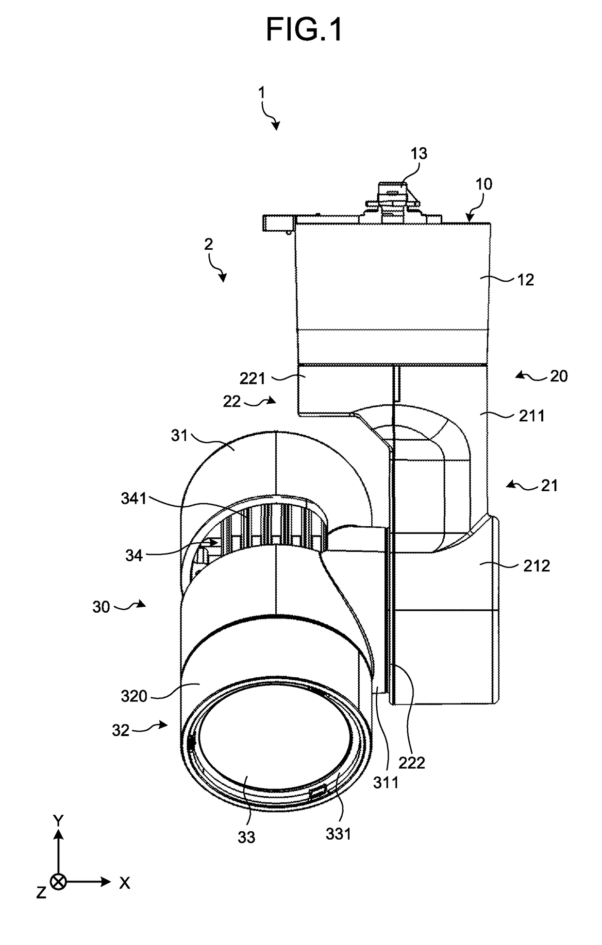
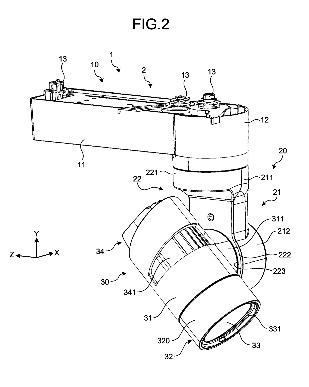
[0032]First, with reference to FIGS. 1 and 2, an overview of the configuration of the lighting apparatus 1 will be described. FIG. 1 is a front view of the lighting apparatus 1. FIG. 2 is a perspective view of the lighting apparatus 1 viewed from the light source unit 30 side.

[0033]In the following description, the direction along the rotation axis (hereinafter also referred to as “first rotation axis”) of an arm portion 20 which will be described later is defined as a Y axis, and an X axis and a Z axis are defined as axes that are orthogonal within a plane orthogonal to the Y axis. For example, the X axis is the direction along the rotation axis (hereinafter also referred to as “second rotation axis”) of the light source unit 30 in the position (initial position) at the time of installing the lighting apparatus 1.

[0034]The lighting apparatus 1 is provided with the driving device 2 including a supporting portion 10, the arm portion 20, and the light source unit 30.

[0035]The supporti...


PUM


Abstract

A driving device according to an embodiment includes a supporting portion, an arm portion and a reinforced portion. The supporting portion includes an electrically-driven first drive source. The arm portion is supported by the supporting portion at one end portion in an extending direction and is, by the first drive source, rotatable about a first rotation axis that is along the extending direction, the arm portion including an electrically-driven second drive source. The reinforced portion is provided inside the arm portion and reinforces the arm portion. An object of operation is mounted on another end portion side of the arm portion and is rotatable about a second rotation axis intersecting the extending direction by the second drive source.

Description

CROSS-REFERENCE TO RELATED APPLICATION(S)[0001]The present application claims priority to and incorporates by reference the entire contents of Japanese Patent Application No. 2016-086350 filed in Japan on Apr. 22, 2016.BACKGROUND OF THE INVENTION1. Field of the Invention[0002]The present invention relates to a driving device and to a lighting apparatus provided therewith.2. Description of the Related Art[0003]Conventionally, provided has been a lighting apparatus that includes a driving device capable of changing the irradiation direction of a spot light and the like to any desired orientation. Such a lighting apparatus pivotally supports, by an arm extending from a supporting portion mounted on a ceiling surface, a lighting body in a rotatable manner from one lateral side of the lighting body, for example. In this case, rotating the arm pivotally supported by the supporting portion changes the orientation of the lighting body in the horizontal direction (pan direction) and rotating...

Claims


Application Information

Patent Timeline
Patent Type & Authority Applications(United States)
IPC IPC(8): F21V21/15F21V14/00F21V29/76F21S8/04F21V21/28F21V21/03
CPCF21V21/15F21S8/043F21V29/763F21V21/28F21V14/00F21V21/03F21S8/00F21V14/02F21V21/26F21V23/003F21V29/503F21V29/76F21V31/005F21V14/06F21V21/35
Inventor MATSUI, NOBUKI
Owner MINEBEAMITSUMI INC
Why Eureka
Try Eureka