Tactile sensor module and method of mounting tactile sensor

a technology of tactile sensor and module, which is applied in the field of tactile sensor, can solve the problems of increasing complexity and increasing manufacturing costs, and achieve the effects of reducing costs, increasing costs, and easy construction of tactile sensors

Active Publication Date: 2009-05-28
NAT INST OF ADVANCED IND SCI & TECH
View PDF7 Cites 13 Cited by
  • Summary
  • Abstract
  • Description
  • Claims
  • Application Information

AI Technical Summary

Benefits of technology

[0033]The tactile sensor module of the present invention is comprised of a strip-shaped flexible substrate that can be folded and/or cut. Density adjustment, mounting region adjustment, and adaptation to arbitrary curved surfaces are therefore possible with one type and cost reductions for the tactile sensor can be made. Conventional tactile sensors could not have their density adjusted and could not be adapted for arbitrary curved surfaces. This necessitated the use of individual flexible substrates, which contributed to increased costs. The tactile sensor module of the present invention can be mounted on an arbitrary curved surface and can therefore be widely applied as tactile sensors for robots and to pressure distribution measurements for cha

Problems solved by technology

Complexity increases as the number of types of mod

Method used


Image

  • Tactile sensor module and method of mounting tactile sensor
  • Tactile sensor module and method of mounting tactile sensor
  • Tactile sensor module and method of mounting tactile sensor

Examples


first embodiment

[F] H-Shaped Strip Section

[F-1] Overall Configuration of Tactile Sensor Module

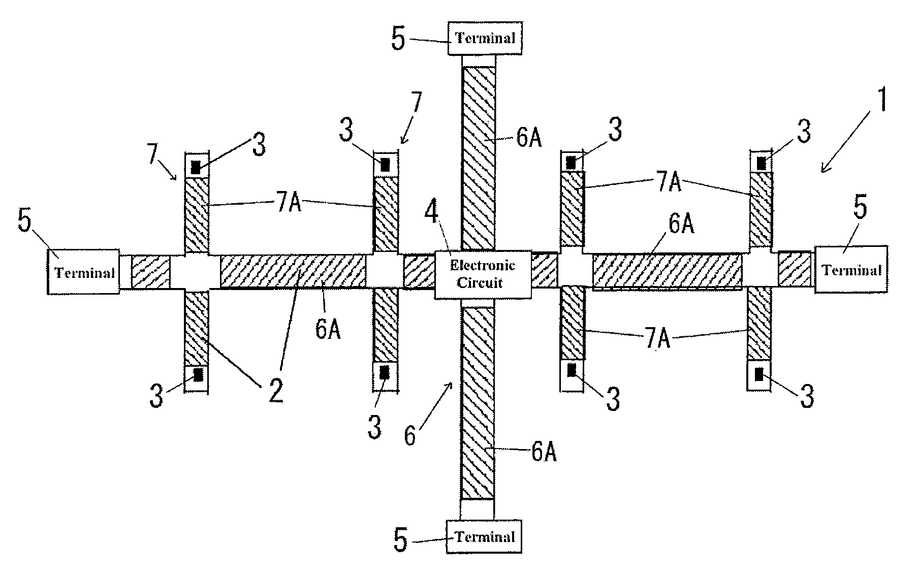
[0076]A description is now given based mainly on FIG. 9 to FIG. 14 of a first embodiment. In the first embodiment, the pressure sensors 3 are provided at strip-shaped body configured from a strip-shaped base section and a plurality of branched strips formed integrally at a distal end of the strip-shaped base section. Specifically, the distal end of the second strip-shaped body 7 is configured from an H-shaped section 9 comprised of a plurality of branched strips. Namely, the second strip-shaped body 7 is comprised of the strip 7A as the strip-shaped base section and the H-shaped section integrally provided at the distal end of the strip 7A. The proximal end of the strip 7A is connected to the strip 6A of the first strip-shaped body 6. The H-shaped section 9 is comprised of two strip-shaped sensing element mounting portions 90, 91 and a strip-shaped connecting portion connecting intermediate portions of two...

example

[F-7] Example

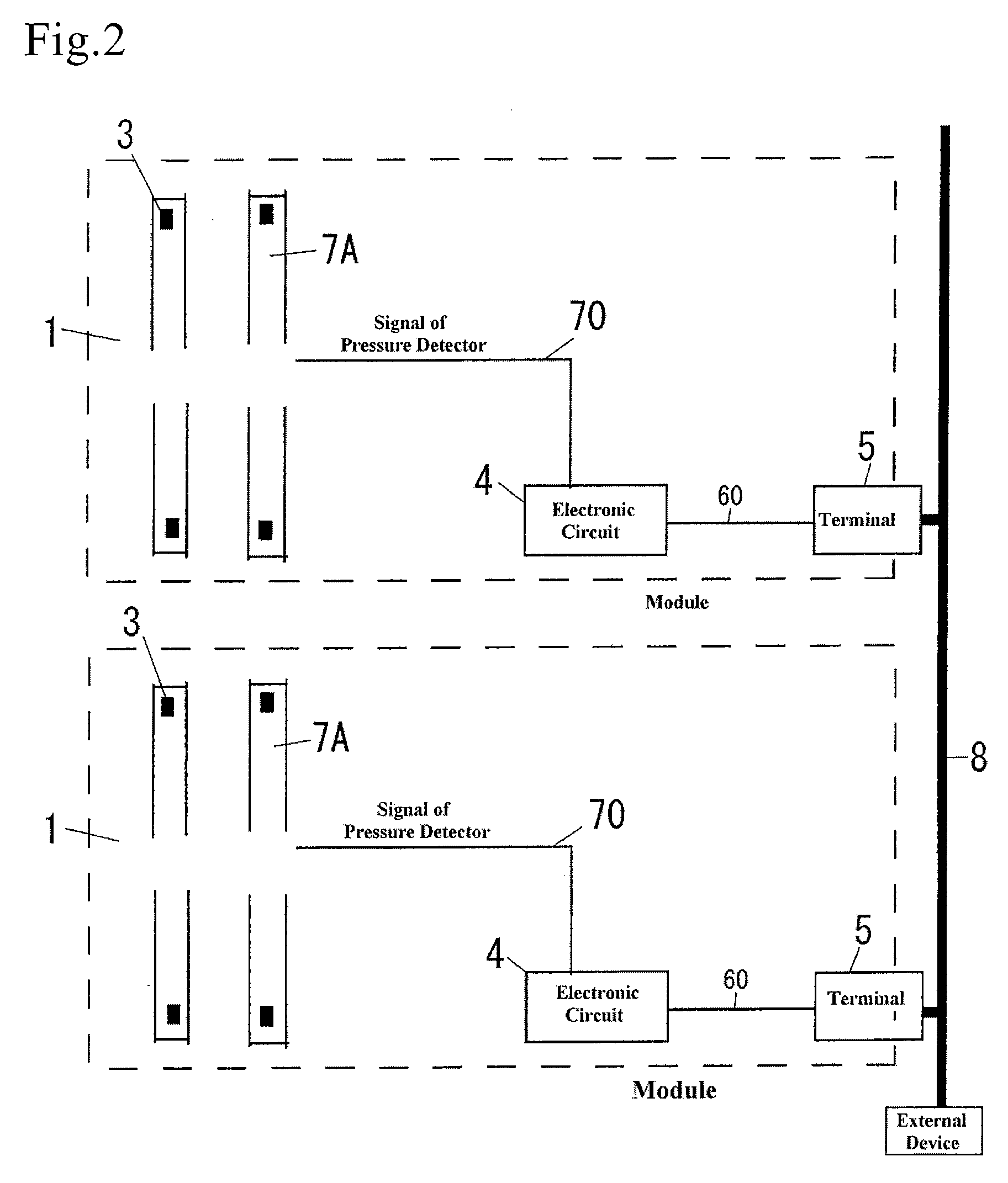
[0093]A description is now given of experimental examples of small-size tactile sensors employing the reflective photointerrupters and urethane shown in the first embodiment. A tactile sensor module is designed, and experiments are carried out regarding sensor functions, communication functions, and functions for connecting between modules. The tactile sensor module comprises thirty-two tactile sensing elements, an electronic circuit section of an 8051 microcomputer (Silicon Laboratories), and a communication terminal capable of connecting the modules. These elements are provided on single flexible substrate such that the module can function by itself as well as function when a plurality of modules are connected together. Four AD converters are prepared for the thirty-two tactile sensing elements and are shared by each eight channels of tactile sensing elements. The four AD converters and the eight channels of LED switches are implemented within a microcontroller. Excel...

second embodiment

[0098][G] Flexible Substrate with a High Degree of Freedom of Arrangement for the Sensing Elements

[0099]An example of changing the substrate shape of the first embodiment is shown. The flexible substrate of the second embodiment is configured from a star structure where a number of strips are coupled together at the base end side. As shown in FIG. 15A, a rectangular flexible substrate is cut vertically in eight places so as to give ten strips, at the center of which the electronic circuit section 4 is located. A communication terminal 5 is provided at a strip 10A at the lower side of the center, with photointerrupters then being arranged at the end portions of the other nine strips 10. By then just folding each strip once in the middle portion, it is possible to arrange the reflective photointerrupters 30 at substantially arbitrary positions within a region on the inside of a circle of a radius of a dimension between the base end sections (bases of the cuts) of the strips 10 and the...


PUM


Abstract

The invention provides a tactile sensor module that enables adjustment of the density of sensing elements and adjustment of mounting regions to be carried out in a straightforward manner with one type of module that is highly adaptive to complex curved surfaces. A tactile sensor module comprises a flexible substrate having one or a plurality of strips, a plurality of sensing elements arranged at the one or plurality of strips of the flexible substrate, one or more communication terminals provided at the flexible substrate; and at least one electronic circuit section provided at the flexible substrate having communication functions. At least one of the strips comprises a foldable region and/or a cuttable region.

Description

FIELD OF THE INVENTION[0001]The present invention relates to a tactile sensor, and particularly relates to a tactile sensor capable of being mounted to arbitrary curved surfaces.BACKGROUND OF THE INVENTION[0002]The need for tactile sensors distributed over the whole body has been increasing in the field of robots and humanoids. Whole body tactile sensors are tactile sensors that make it possible to provide tactile sense to the whole of a system. Most of research regarding tactile sensors relates to single sensor characteristics. The target of the research is how to detect characteristics for fineness of hand such as smooth or rough. The research is also taking place into how to give an input interface of a computer a sense of touch. According to most of the tactile sensor research in the related art, importance has been placed on the characteristics obtained. However, from the point of view of implementation of tactile sensors, application to the appropriate curved shape, ease of ma...

Claims


Application Information

Patent Timeline
IPC IPC(8): G01J1/56G01D7/00
CPCG01L1/205G01L5/228G01L1/24G01L5/00
Inventor KUNIYOSHI, YASUOOHMURA, YOSHIYUKISETA, NAOKONAGAKUBO, AKIHIKO
Owner NAT INST OF ADVANCED IND SCI & TECH
Why Eureka
Try Eureka