
Pulsed plasma drive electromagnetic motor generator

a technology of electromagnetic motor and pulsed plasma, which is applied in the direction of transportation and packaging, instruments, containers, etc., can solve the problems of reducing efficiency, adding heating, and sparking by itself,

Inactive Publication Date: 2001-08-07
ARNOLD CHRISTOPHER J
View PDF27 Cites 27 Cited by
  • Summary
  • Abstract
  • Description
  • Claims
  • Application Information

AI Technical Summary

Problems solved by technology

The common physical effects include hysteresis, inductive and conductive heating in the armature and rotor facilitating the need for heavy gauge 600 degree insulated conductors, special heat resistant bonding agents, and air flow cooling means which further reduces efficiency.
Sparking by itself adds to commutator erosion and added heating, also requiring cooling.
Likewise the effects of the Collapsing Magnetic Field, further referred to as CMF, is caused when a complete break in the circuit occurs at the commutator resulting in conductor erosion and copious heat production.
(a) When a motor / generator uses laminate steel as an armature or coil support, it is these laminates which add useless weight, carry eddy currents & interfere with permanent and generated magnetic fields.
This resulted in high internal heat which proved problematic for the high BH.sub.max permanent magnets otherwise known as neodymium iron boron, having a relative low curie point.
(d) U.S. Pat. No. 5,861,693 Takahashi: Yoshiaki (Jan. 19, 1999) is for a motor using now conventional components such as high BH.sub.max permanent magnets, however its use of steel laminates causes drag within the high strength magnetic fields, creating useless heat and further built-in inefficiencies to overcome.
(b) Previous commutation means lead to suppress counter-EMF as it causes magnetic braking which must be overcome by applying higher driving currents to counter its effects, thus causing an increase in system heating resulting in, removal means and requiring excess insulation and increased wire gauge.

Method used


Image

  • Pulsed plasma drive electromagnetic motor generator
  • Pulsed plasma drive electromagnetic motor generator
  • Pulsed plasma drive electromagnetic motor generator

Examples


Embodiment Construction

--Description

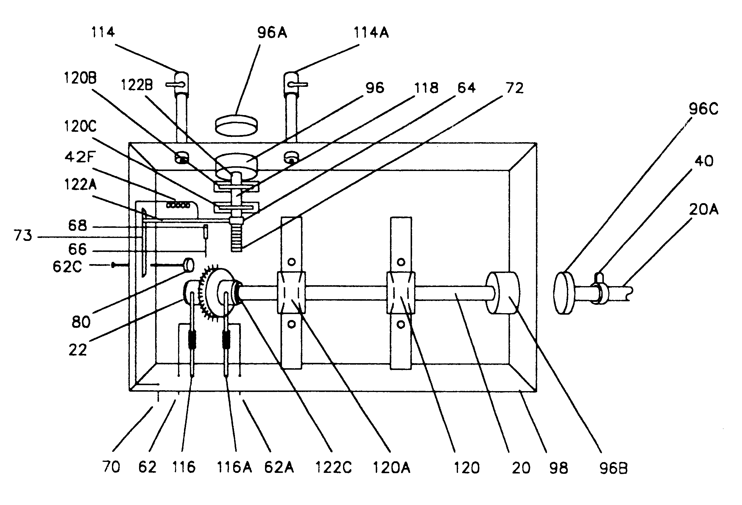
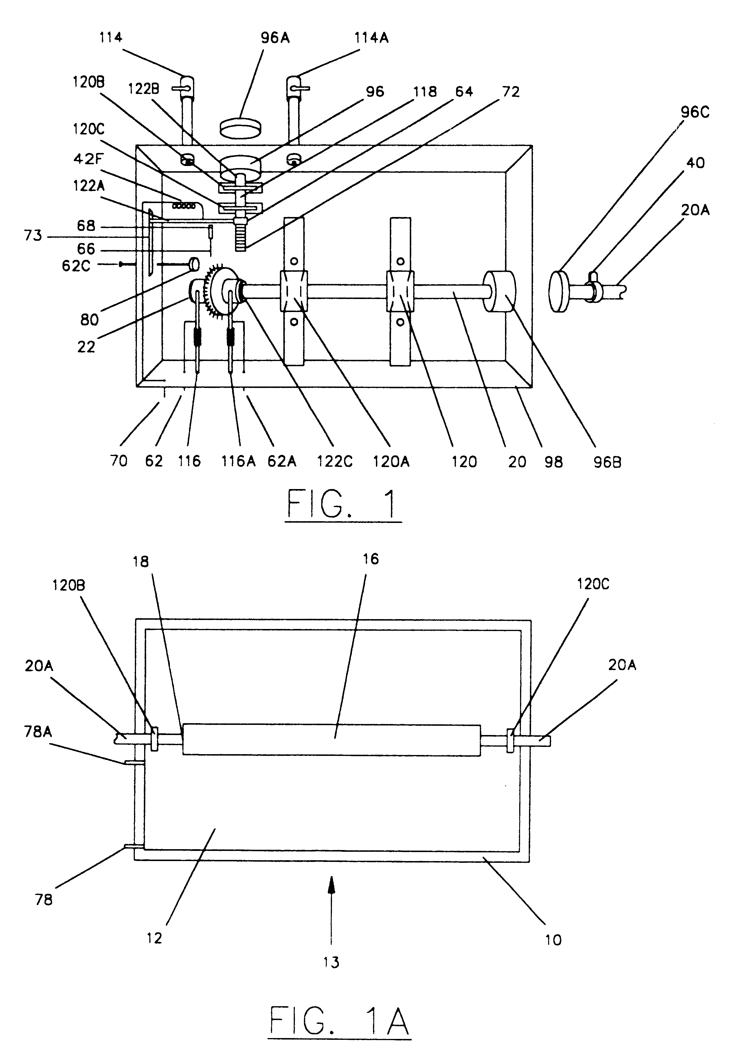
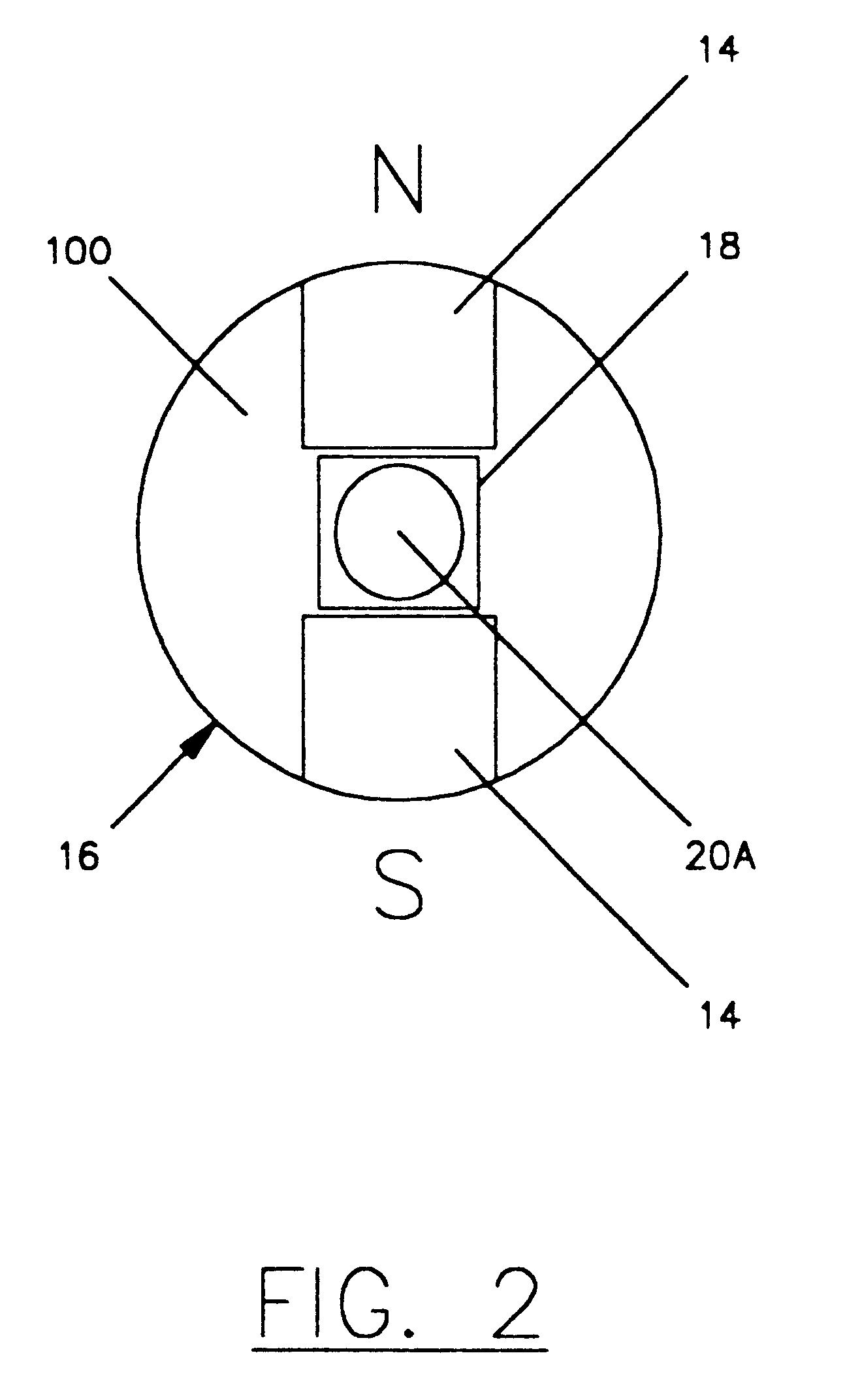
Referring to FIG. 1, a power generating electromagnetic motor 9 consisting of a drive coil assembly 13 attached to a magnetic coupler 96C adjacent to a hermetically sealed container 98, which contains a magnetic coupler 96B so attached at point 122B is a shaft 20 journaled through a bearing 120 and a bearing 120A, at point 122C a novel pulsed plasma commutator 22 as detailed in FIG. 3, is secured by a tube retainer 74 in a shaft insulator tube 26 so affixed is a non conductive disk 24, thereon its peripheral face 36 is an arched lobe 32 holding radial contacts 38, said arched lobe 32 is affixed to a conductor wire 42 so affixed to an annular conductive ring 28 in sliding contact with a ring contact bar 46 so affixed to a tension bar 50 so attached to said conductor wire 42 ending at terminal 62 and said tension bar 50 is attached to a tension spring 54 terminating at post 116. Counterpoised to said arched lobe 32 on said peripheral face 36 are radial contacts 38A so aff...


PUM


Abstract

A power generating electromagnetic motor (2) which comprises a novel pulsed plasma commutator (22) in conjunction with a bipolar magnetic rotor (16) made of high BH.sub.max permanent magnets (14) affixed to a core element (18) disposed coaxially with drive coil (12) with an air gap there between and providing an adjacent receiving coil (10) for discrete, particle and wave recapture as well as by array (80). The commutator (22) propels the drive coil assembly (8) with a series of intermittent pulses as well as producing unique power outputs and discrete particles and waves in the resultant plasma, such as Electrum Validum or EV and furthermore is the unique presence of system negative entropy.

Description

BACKGROUND--FIELD OF INVENTIONThis invention relates to spark control on the commutator, specifically zero spark suppression whereby full cycle sparking and plasma streams with resultant charge clusters, radiation, electromotive force, discrete wave and discrete particle generation are achieved.BACKGROUND--DESCRIPTION OF PRIOR ARTAll previous commutators used in DC motors or generators have been designed to reduce sparking by elaborate means whereby no examples are referable as similar, only contrary by means. Traditional design goals have been to reduce commutator sparking, yet complete suppression seems to be mythical. The common physical effects include hysteresis, inductive and conductive heating in the armature and rotor facilitating the need for heavy gauge 600 degree insulated conductors, special heat resistant bonding agents, and air flow cooling means which further reduces efficiency. Sparking by itself adds to commutator erosion and added heating, also requiring cooling. C...

Claims


Application Information

Patent Timeline
Patent Type & Authority Patents(United States)
IPC IPC(8): H01R39/00H02K53/00H02K13/00H01R39/04
CPCH01R39/04H02K53/00H02K13/006
Inventor ARNOLD, CHRISTOPHER J.
Owner ARNOLD CHRISTOPHER J
Learn More