Tool for mounting disk valves in motor cylinder heads
- Summary
- Abstract
- Description
- Claims
- Application Information
AI Technical Summary
Problems solved by technology
Method used
Image
Examples
Embodiment Construction
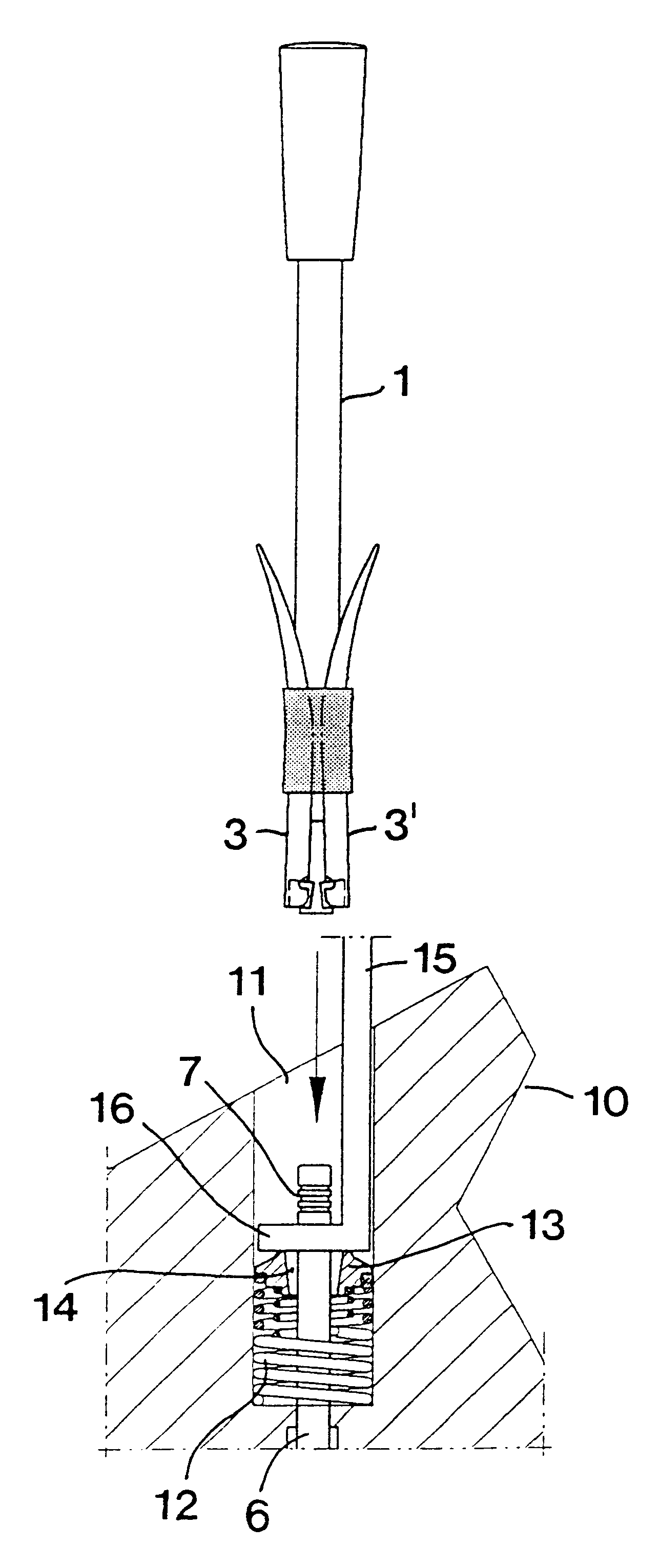
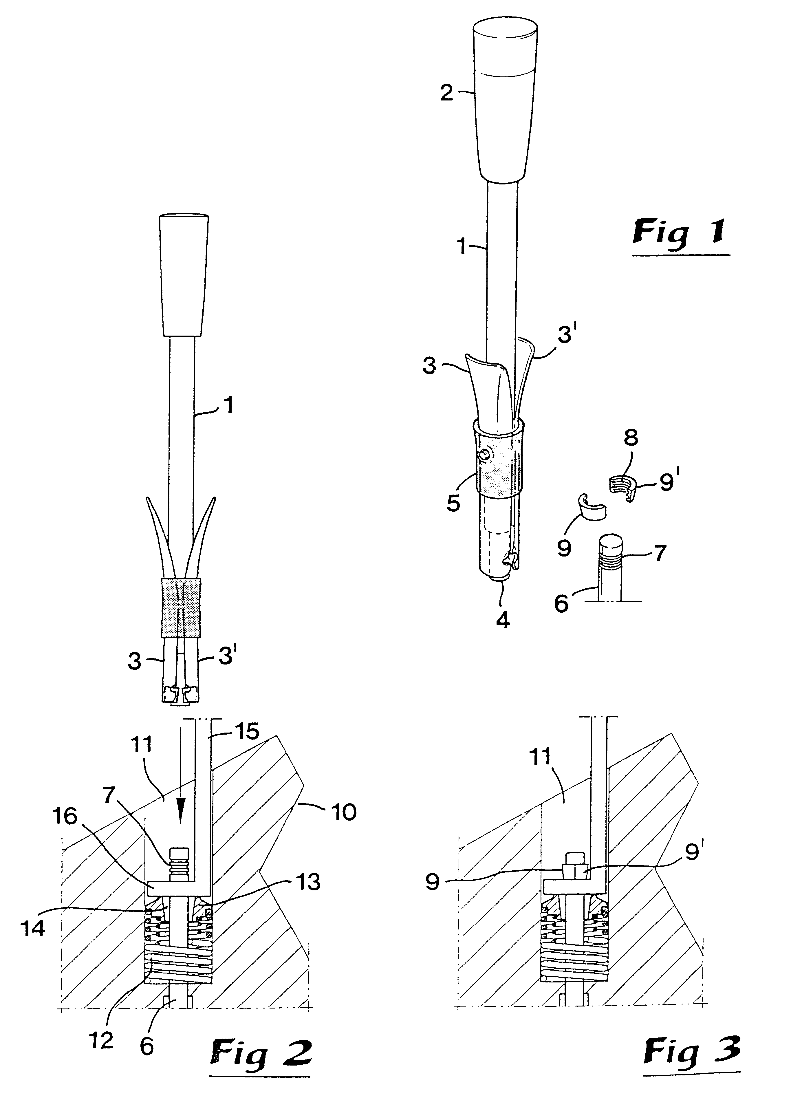
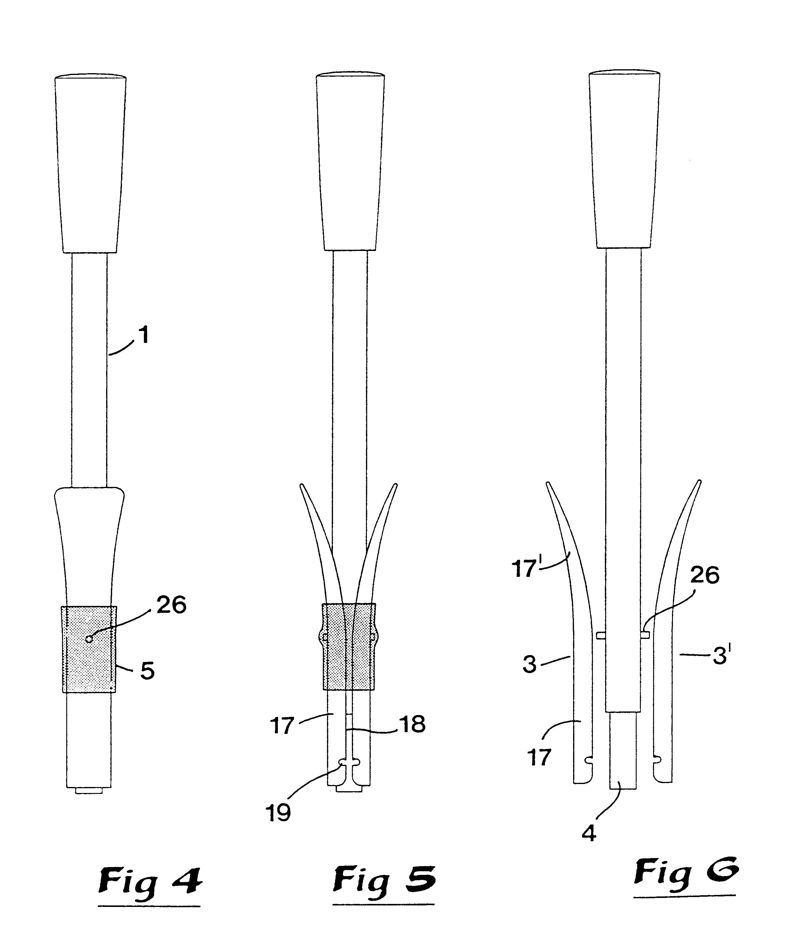
The tool shown in FIG. 1 comprises a shaft 1 which at one end has a handle-like cap 2 and at its opposed end comprises two clamping arms 3, 3'. In practice, the shaft 1 may consist of a metal tube with a cylindrical envelope surface. In a cavity in the front end (directed downwards in FIG. 1) of the shaft tube there is introduced a cylinder-shaped tap 4 that is spring-loaded, more specifically by a not shown spring mounted in the cavity, which spring steadily strives to bring out the tap to an outer end position. In other terms, the pressing-in of the tap into the cavity takes place against the action of this spring. The two clamping arms 3, 3', which will be described in more detail with reference to FIGS. 4 to 10, are enclosed by an elastic sleeve 5, which forms a spring means that steadily strives to keep the front parts of the arms springingly pressed against the envelope surface of the shaft.
In FIG. 1, also an upper end of a valve rod 6 is shown, which in a manner known per se ...
PUM
| Property | Measurement | Unit |
|---|---|---|
| Angle | aaaaa | aaaaa |
| Angle | aaaaa | aaaaa |
Abstract
Description
Claims
Application Information
 - R&D
- Intellectual Property
- Life Sciences
- Materials
- Tech Scout
- Unparalleled Data Quality
- Higher Quality Content
- 60% Fewer Hallucinations
Browse by: Latest US Patents, China's latest patents, Technical Efficacy Thesaurus, Application Domain, Technology Topic, Popular Technical Reports.
© 2025 PatSnap. All rights reserved.Legal|Privacy policy|Modern Slavery Act Transparency Statement|Sitemap|About US| Contact US: help@patsnap.com


