Apparatus for forming a leno weave

a technology of leno weaving and apron, which is applied in the direction of weaving, leno shedding mechanism, textiles and paper, etc., can solve the problem of relatively high cost of the apparatus

Inactive Publication Date: 2002-05-07
SULZER TEXTIL AG
View PDF10 Cites 18 Cited by
  • Summary
  • Abstract
  • Description
  • Claims
  • Application Information

AI Technical Summary

Problems solved by technology

Disadvantageous in this known arrangement is that the apparatus is relatively expensive.

Method used


Image

  • Apparatus for forming a leno weave
  • Apparatus for forming a leno weave
  • Apparatus for forming a leno weave

Examples


first embodiment

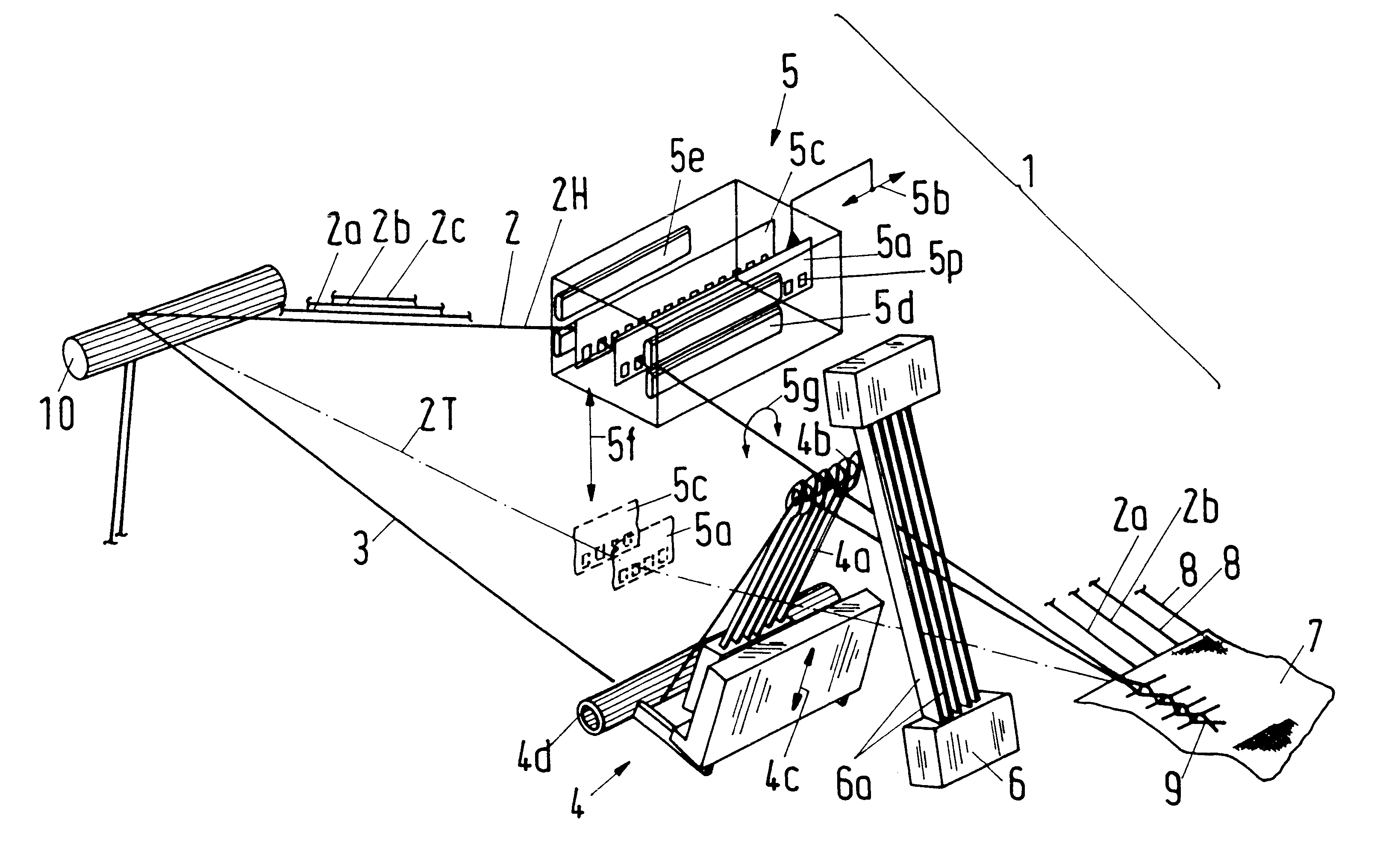
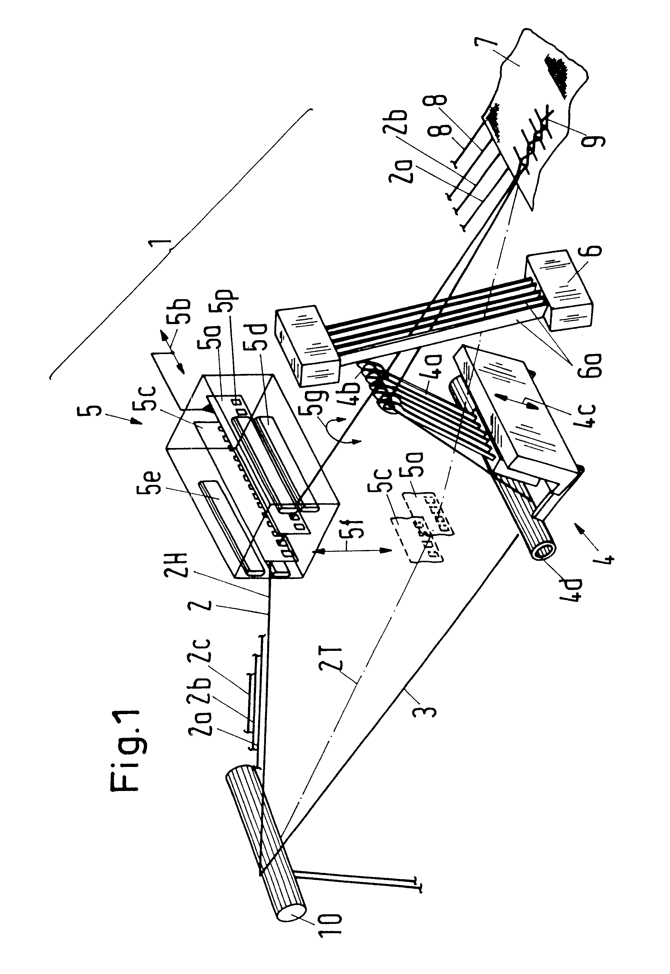
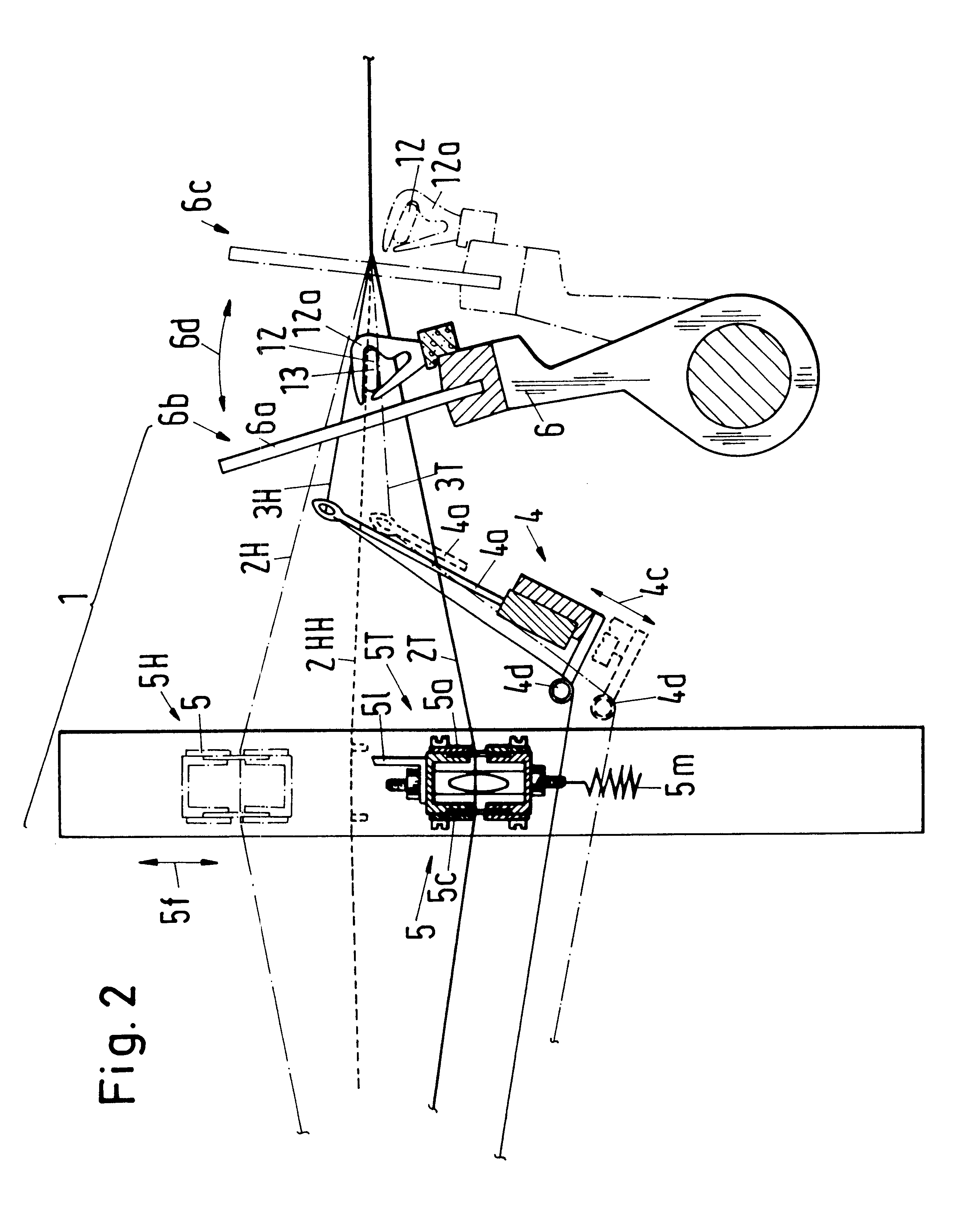
FIG. 2 shows a side view of the apparatus 1 for forming a leno edge. The leno thread displacing apparatus 5 is at first in a low position 5T, so that the leno thread 2T is held in the low position. The ground thread needle bar 4 is arranged stationary in the first embodiment and holds the ground thread 3H in the high position, so that a shed is formed between the leno thread 2T and the ground thread 3H into which a projectile which inserts a weft thread 13 can be introduced which is guided by a projectile guiding apparatus 12a. Then the reed 6 with lamella 6a is beat up against the cloth edge in the direction of movement 6d so that the reed is in the beat-up position 6c. After the completion of the beating up the reed 6 is again brought back into the open position 6b travelling in the direction of movement 6d. During the beating up of the reed 6 and the succeeding moving into the open position 6b the leno thread displacing apparatus 5 executes a rerouting movement in which the leno ...

second embodiment

In a second embodiment the ground thread needle bar 4, as is illustrated in broken lines in FIG. 2, is also displaceably mounted in the direction of movement 4c. In this the ground thread needle bar 4 is transferred after a completed weft insertion from the upper position into the lower position, which is illustrated in chain-dotted lines. And the leno thread displacing apparatus 5 is lifted up in the vertical direction 5f until the leno thread 2T comes to lie higher in the vertical direction than the ground thread needles 4a, as is illustrated by the leno thread 2HH, which is illustrated with a broken line. In contrast to the above-described arrangement, the leno thread displacing apparatus 5 need in this case travel only about one-half the vertical distance, so that the displaceably mounted ground thread needle bar 4 has the advantage that a new shed can be produced with a smaller movement of the leno thread displacing apparatus 5, which for example permits a more rapid weaving.

FI...


PUM


Abstract

Apparatus for forming a leno weave from a leno thread and a ground thread. The apparatus includes a reed for guiding the leno thread and the ground thread, and a needle bar with ground thread needles for guiding the ground thread. The needle bar also includes a movably mounted leno thread displacing apparatus, with the needle bar and the leno thread displacing apparatus being arranged ahead of the reed. The leno thread displacing apparatus includes a laying element that is displaceably mounted in a displacement direction that extends substantially parallel to the direction of extent for the reed. The laying element includes guiding apparatus for guiding the leno thread. The leno thread displacing apparatus is movably mounted in a direction of movement that extends transversely to the direction of extent of the reed, in particular, in a substantially vertically extending direction, in order to move the leno thread both in the displacement direction and in the direction of movement.

Description

1. Field of the InventionThe invention relates to an apparatus for forming a leno weave.2. Description of the Prior ArtAn apparatus for forming a leno weave is known from the specification WO 98 / 07913. In addition to a ground thread needle bar, which is providede for holding the ground thread, this apparatus comprises three further head frames for holding the leno thread. A first frame contains a longitudinal rail with small, obliquely extending slits for receiving the leno thread. A further frame contains a longitudinal rail with a groove which extends over the entire cloth width for guiding all leno threads. The third frame has a pivotal arrangement in order to tension the leno threads so that the leno threads move in the oblique slits of the first frame in the direction of the cloth width. Disadvantageous in this known arrangement is that the apparatus is relatively expensive.The object of the present invention is to propose an economically more advantageous apparatus for forming...

Claims


Application Information

Patent Timeline
Patent Type & Authority Patents(United States)
IPC IPC(8): D03C7/00D03C7/06
CPCD03C7/06D03C7/00
Inventor HERZIG, MARCEL
Owner SULZER TEXTIL AG
Why Eureka
Try Eureka