Radio communication apparatus of diversity transmission system

US6396821B1Inactive Publication Date: 2002-05-28KK TOSHIBA

Image

  • Radio communication apparatus of diversity transmission system
  • Radio communication apparatus of diversity transmission system
  • Radio communication apparatus of diversity transmission system

Examples


Embodiment Construction

An embodiment of a radio communication apparatus according to the present invention will now be described with reference to the accompanying drawings.

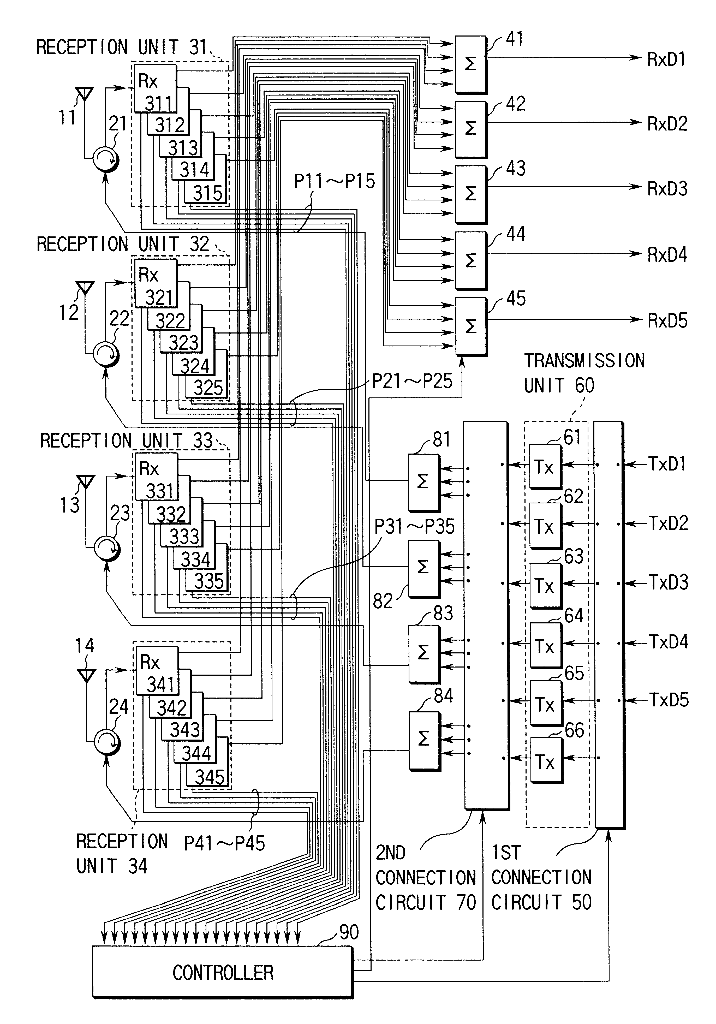
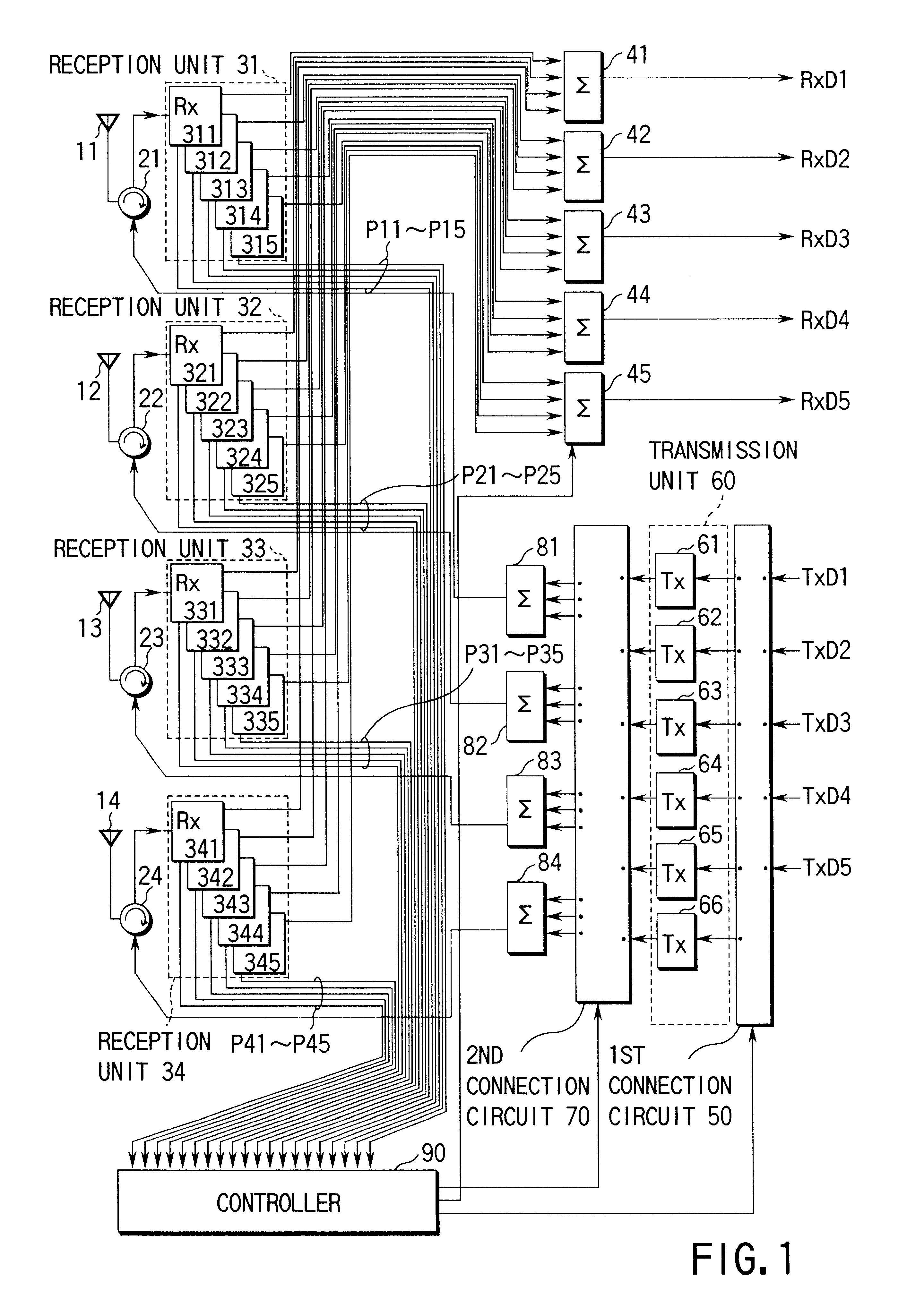
FIG. 1 shows the structure of equipment-relating to a diversity transmission function of a base station for mobile communication of CDMA system according to the embodiment of the invention. In this embodiment, the number of diversity antennas is four and the number of multiplexed channels is five.

The communication apparatus of the base station has four diversity antennas 11 to 14 provided at different locations, e.g. four corners of a square. It is known that a diversity effect can be obtained if the distance between antennas is about 1 / 4 or more of the wavelength. The antennas 11 to 14 are connected to transmission / reception switching circuits 21 to 24; respectively. Each transmission / reception switching circuit 21 to 24 comprises, e.g. a circulator which corresponds to a time division duplex system (TDD) in which a transmission signa...


PUM


Abstract

A radio communication apparatus with a diversity transmission function is provided with an auxiliary transmitter Further to transmitters peculiar to channels. CDMA system signals received by antennas are modulated for respective channels, a maximum reception power level of each channel is detected, and an antenna with a maximum level is found. In a diversity transmission control, it is determined whether or not maximum reception levels of all channels are equal to or higher than a predetermined level. If the maximum reception levels of all channels are equal to or higher than the predetermined level, an ordinary diversity control is performed. Specifically, transmission signals of respective channels are transmitted from antennas with maximum reception power levels via the transmitters peculiar to the channels. If the maximum reception level of any one of the channels is the predetermined level or less, the transmission signal of the associated channel is transmitted from the antenna with a second highest reception power level of the channel via the auxiliary transmitter, Further to the ordinary diversity control.

Description

The present invention relates to a radio communication apparatus in which a transmission antenna is selected by a diversity transmission system.In the field of mobile communications, a diversity technique is used to prevent degradation of communication quality due to phasing, etc. An example of the diversity technique is a diversity transmission system adopted in a base station of PHS (personal Handyphone System).In the diversity transmission system, a plurality of antennas are provided and a transmission signal from a mobile station (radio communication terminal) is received by the plural antennas. On the basis of reception results by the plural antennas, an antenna with highest communication quality is found and a signal is transmitted to the mobile station from this antenna. This system is advantageous in that since the antenna is selected on the basis of the degree of phasing at antenna, there is no load on the mobile station side.However, if the diversity transmission system is...

Claims


Application Information

Patent Timeline
28 May 2002
Publication
US6396821B1
IPC
H04B7/04; H04B7/08; H04L1/02; H04B7/06; H04L1/06
CPC
H04B7/0608; H04L1/06; H04B7/082; Y02D30/70
Inventors
TAKAHASHI, HIDEHIRO