Decorative light plug

a technology of decorative light and plug-in, which is applied in the direction of electrical discharge lamps, coupling device connections, lighting and heating apparatus, etc., can solve the problems of waste of materials and trouble, and achieve the effect of reducing the waste of materials

Inactive Publication Date: 2002-06-11
FAN WONG TSUI TUAN
View PDF5 Cites 10 Cited by
  • Summary
  • Abstract
  • Description
  • Claims
  • Application Information

AI Technical Summary

Problems solved by technology

When the decorative light of this kind is to be extended, the user will have to cut off the plug (4) and reconnect the distal end of the decorative light with a distal end of another decorative light, which is not only troublesome, but also a waste of material.

Method used


Image

  • Decorative light plug
  • Decorative light plug
  • Decorative light plug

Examples


Embodiment Construction

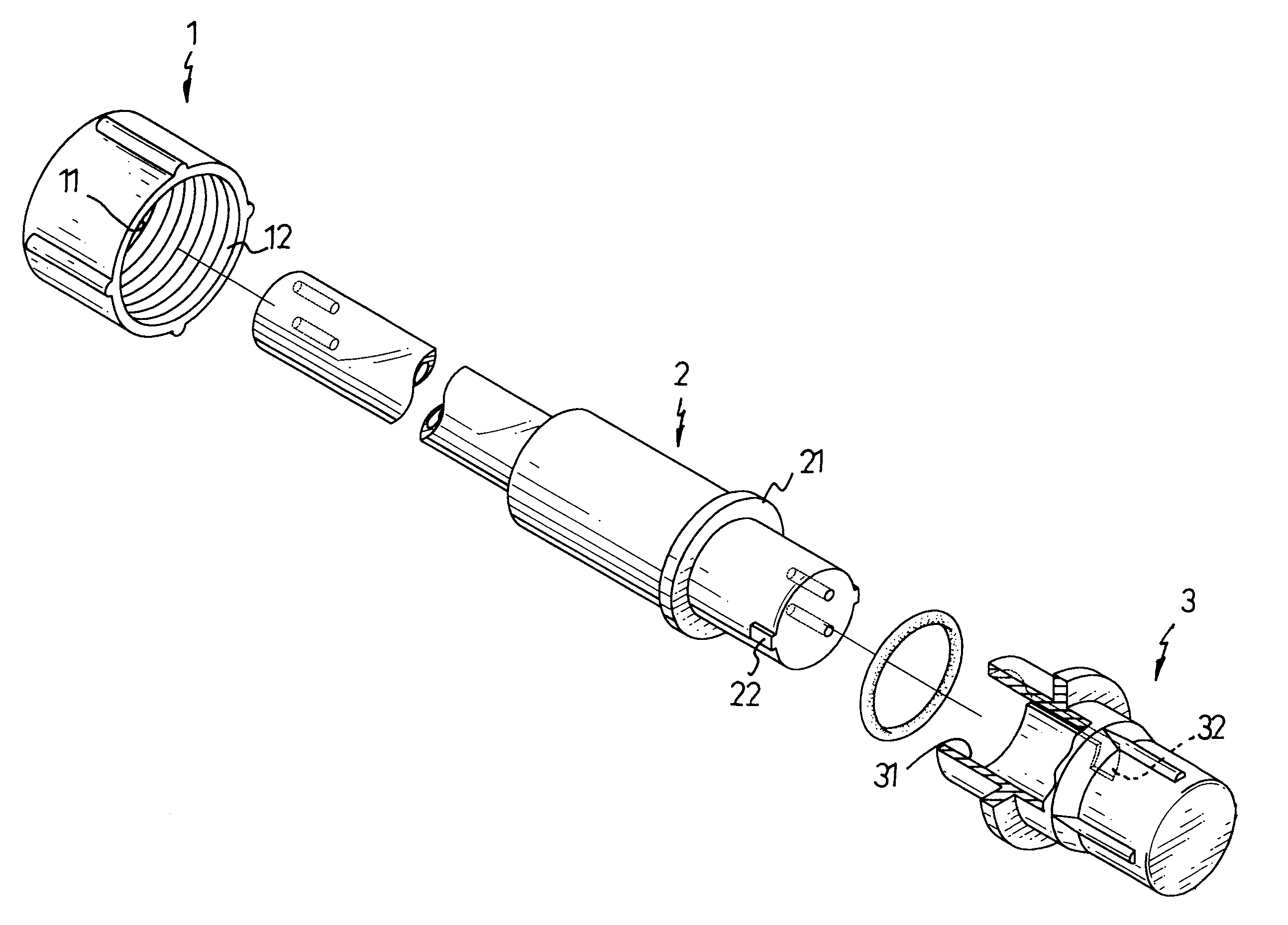
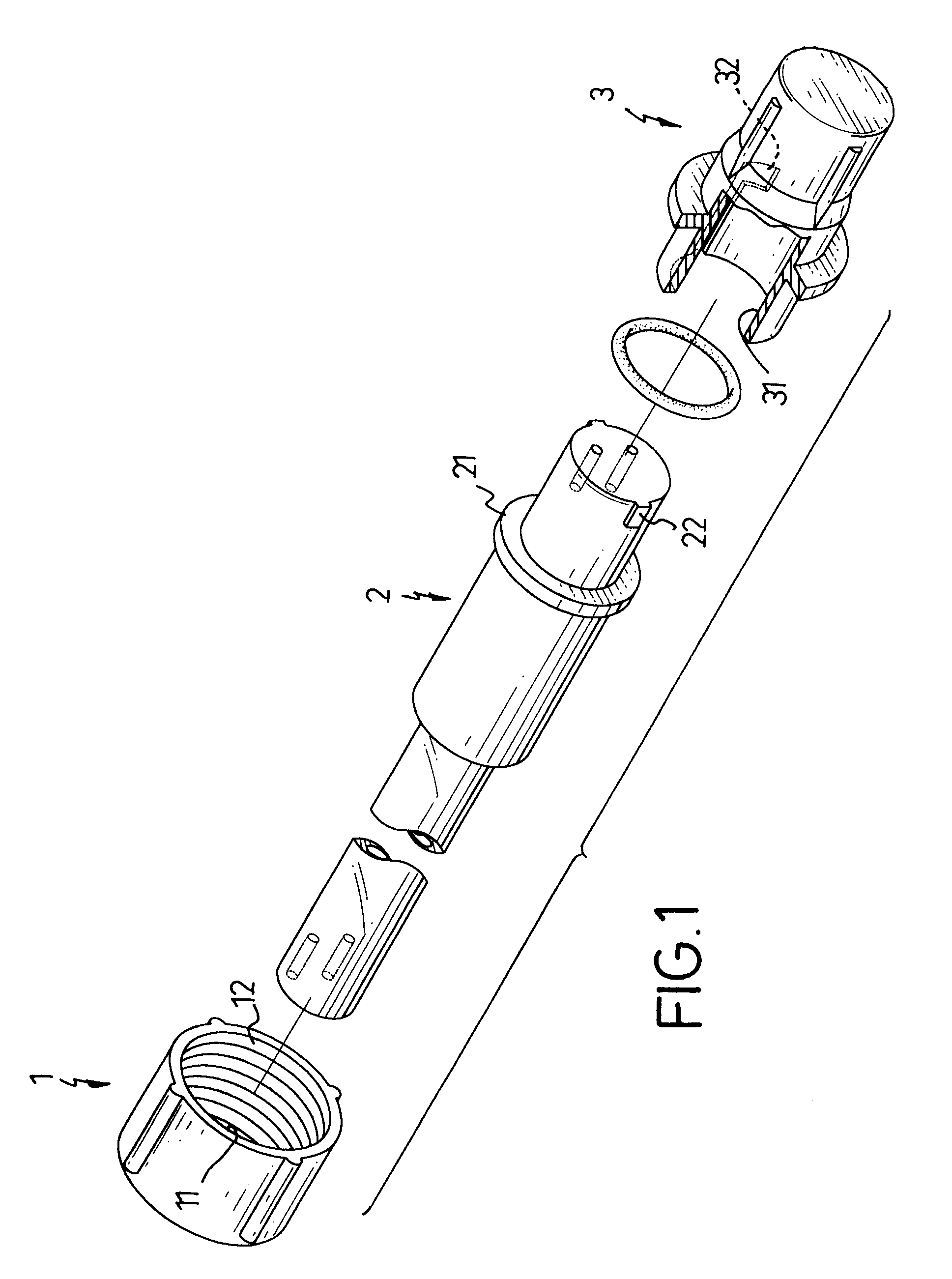
With reference to FIG. 1, the decorative light plug has a collar (1), a female connector (2) and a cover (3).

The collar (1) has a through hole (11) defined through the collar (1) and inner thread (12). The collar is slidably retained on the decorative light.

The female connector (2) is integrally formed on a distal end of the decorative light and has a flange (21) formed on an outer periphery of the female connector (2) and a pair of keys (22) formed on opposite sides of the distal end of the female connector (2).

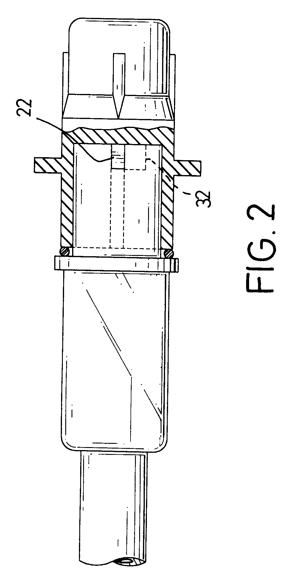
The cover (3) has a blind hole (31) defined to enclose the distal end of the decorative light and a pair of L-shaped keyways (32) formed on an inner face defining the blind hole (31) and corresponding to the pair of opposed keys (22).

When the decorative light of the invention is not in use, the user may use the cover (3) to engage with the decorative light by inserting the keys into the corresponding L-shaped keyways (32). After the keys (22) are completely inserted into the...


PUM


Abstract

A decorative light plug has an female connector integrally formed on the decorative light and having a flange formed on an outer periphery of the female connector and a cover having a blind hole defined to enclose a distal end of the decorative light and a pair of L-shaped keyways formed to correspond to a pair of keys formed on the outer periphery of the female connector. After the distal end of the decorative light is inserted into the blind hole of the cover, rotation of the cover will secure the engagement between the cover and the decorative light.

Description

1. Field of the InventionThe present invention relates to a decorative light plug, and more particularly to a decorative light plug detachably connected with a distal end of the decorative light so as to protect the distal end of the decorative light from damage.2. Description of Related ArtA kind of light is made by connecting numerous small light sources in series and coating them with flexible and transparent plastic material so that the light sends out soft light and provides a decorative effect. Since the light sources are connected in parallel, it is important to provide a secure connection between adjacent bulbs. With reference to FIG. 3, a conventional light plug (4) is integrally formed on a distal end of the decorative light to protect the pins (not shown) inside the decorative light from damage. When the decorative light of this kind is to be extended, the user will have to cut off the plug (4) and reconnect the distal end of the decorative light with a distal end of anot...

Claims


Application Information

Patent Timeline
Patent Type & Authority Patents(United States)
IPC IPC(8): F21V15/00F21V19/00H01R13/00H01R13/60H01R13/44H01R13/443H01R33/05H01R33/06
CPCF21V15/00F21V19/0005H01R13/60H01R33/06H01R13/443
Inventor FAN WONG, TSUI-TUAN
Owner FAN WONG TSUI TUAN
Why Eureka
Try Eureka