
Pressing pincer

a pincer and pin-type technology, applied in forging presses, manufacturing tools, shaping tools, etc., can solve the problems of inexact pressing of fittings to tubes, inconvenient sealing of connections, and inability to pivot jaws freely

Inactive Publication Date: 2002-08-20
VON ARX AG
View PDF12 Cites 35 Cited by
  • Summary
  • Abstract
  • Description
  • Claims
  • Application Information

AI Technical Summary

Problems solved by technology

One disadvantage of this pressing pincer is that the pivot jaws are freely pivotable about the bearing bolts with respect to the T-shaped carrier plates.
This results in an inexact pressing of the fittings to the tube.
Furthermore there is a danger that the fitting and / or the tube at the beginning of the pressing are so damaged that a sealing connection is not guaranteed.

Method used


Image

  • Pressing pincer
  • Pressing pincer
  • Pressing pincer

Examples


Embodiment Construction

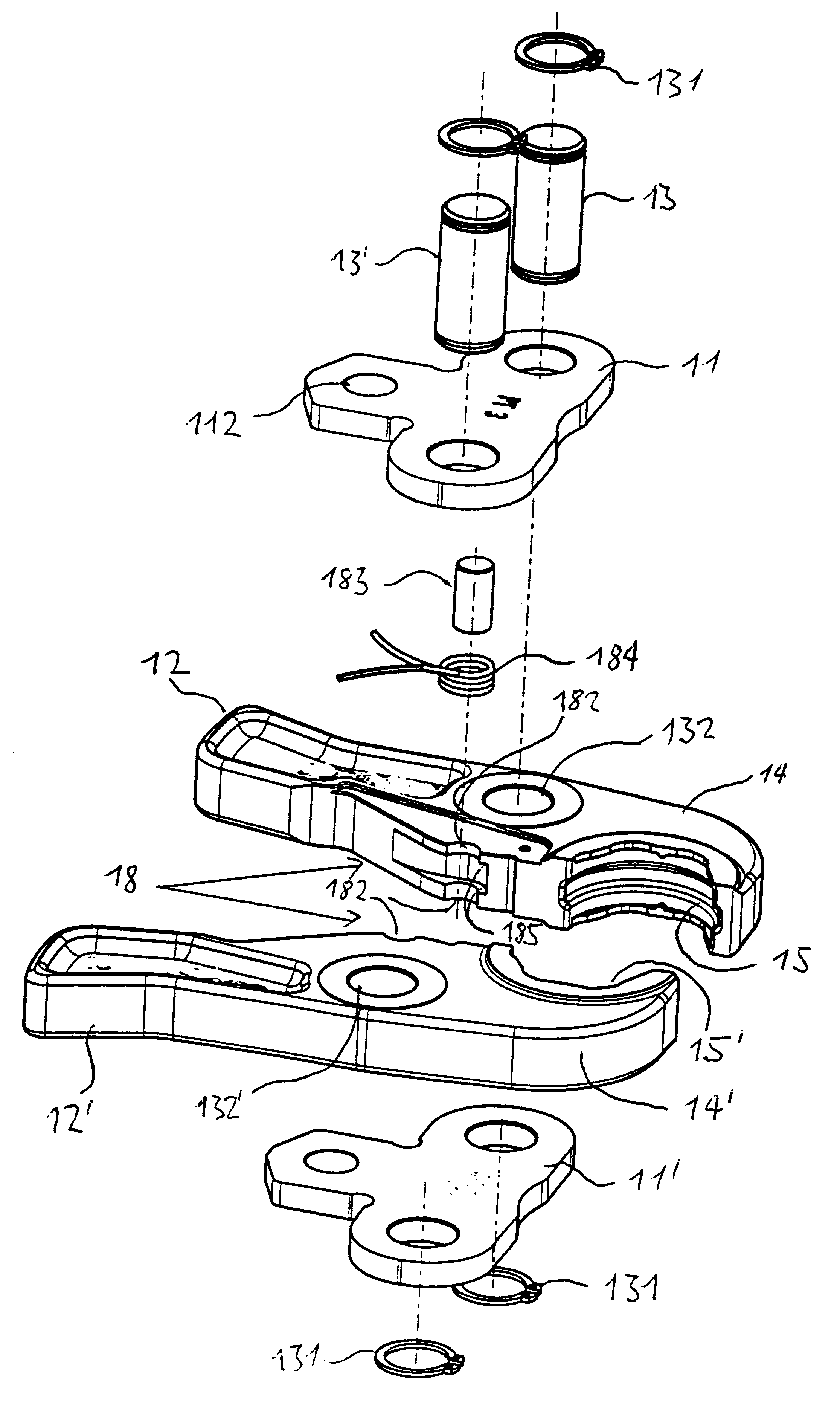
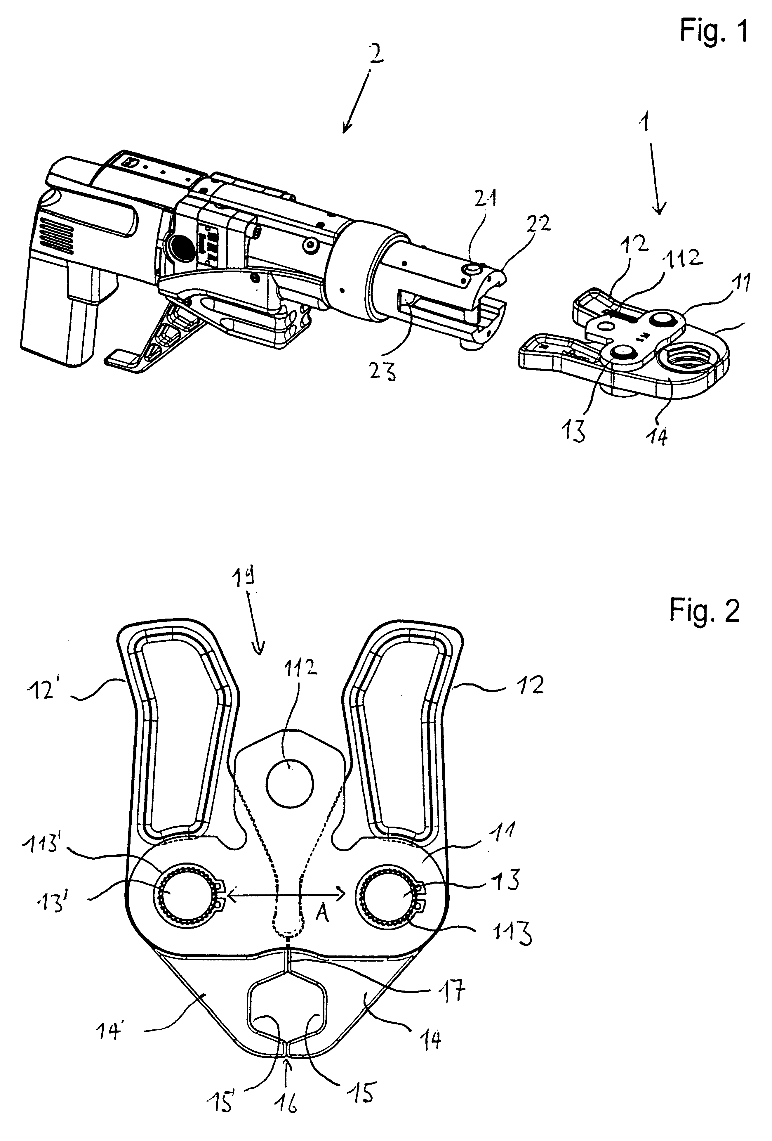
FIG. 1 shows a pressing apparatus with the associated exchangeable pressing pincer, in a perspective top view. The pressing apparatus 2 comprises a drive unit and a connection unit for connection to a pressing pincer 1. The connection unit comprises two holding plates 22. The pressing pincer 1 with two T-shaped carrier plates 11, 11' is inserted between the holding plates 22. A connection bolt 21 is pushed through the holding plates and a receiver opening 112 on the T-shaped carrier plates 11, 11' and is secured. The pressing apparatus 2 is thus ready for use. The pressing pincer 1 then on actuation, with the two pivot arms 12 bears on the bearing surfaces 23 on the pressing apparatus 2. With a further retraction of the pressing pincer 1 the pivot arms 12 are pushed laterally outwards and thus the pressing is undergone.

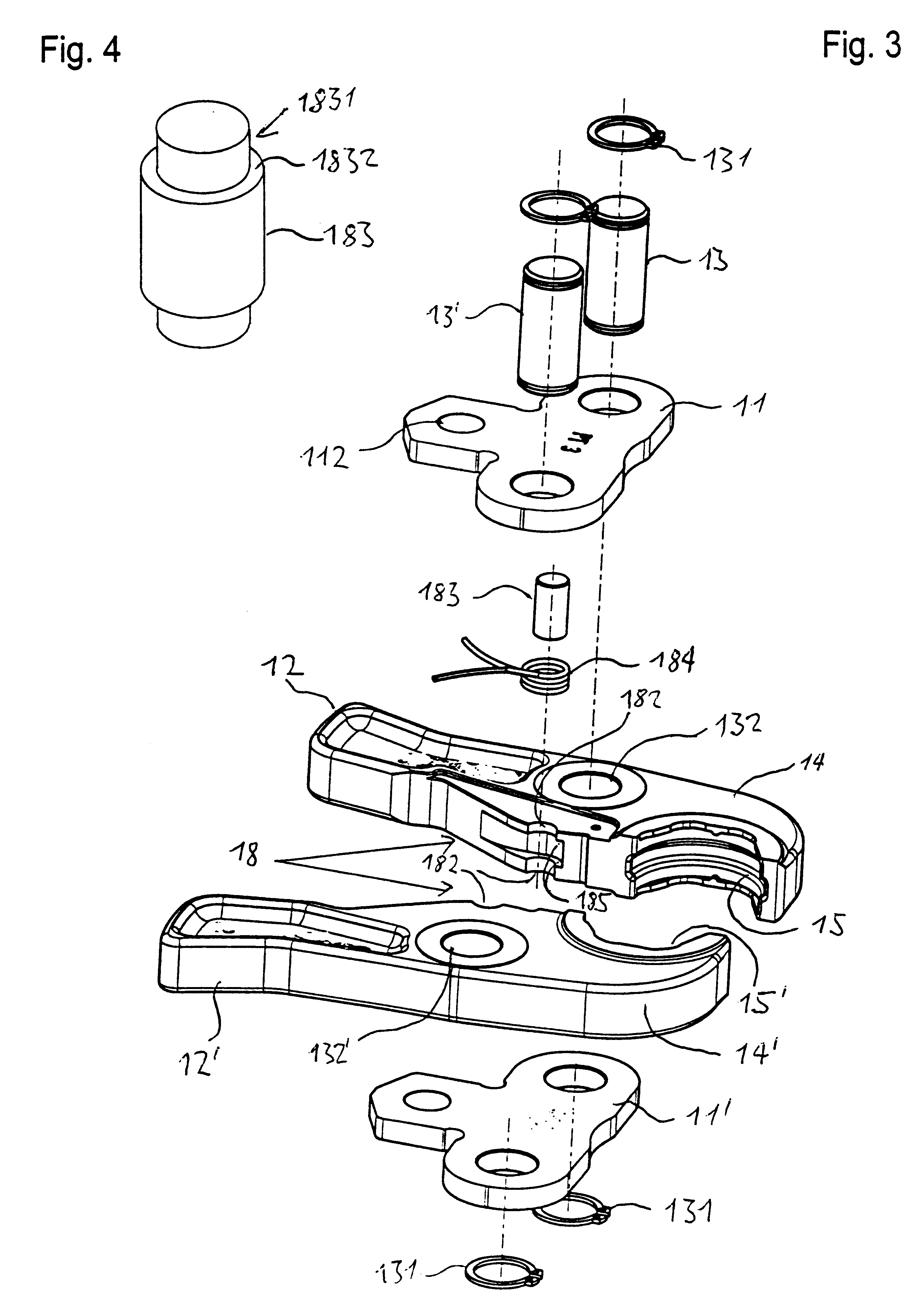
In FIG. 2 the pressing pincer 1 is shown in more detail. The pressing pincer 1 has two T-shaped carrier plates 11, 11'. The carrier plates 11, 11' on the bar piece la...


PUM

PropertyMeasurementUnit
distanceaaaaaaaaaa
circumferenceaaaaaaaaaa
timeaaaaaaaaaa

Abstract

A pressing apparatus with an associated, exchangeable pressing tool. The pressing apparatus has a drive unit and a connection unit for connection to a pressing pincer. The connection unit has two holding plates. The pressing pincer with its two T-shaped carrier plates is inserted between the holding plates. A connection bolt is pushed through the holding plates and a receiving opening on the T-shaped carrier plates and is secured. The pressing apparatus is thus ready for use. The pressing pincer with an actuation bears with its two pivot arms on bearing surfaces on the apparatus. With a further retraction of the pressing pincer the pivot arms are pushed out laterally and thus the pressing is undergone.

Description

1. Field of the InventionThis invention relates to a pressing pincer for a pressing apparatus for connecting a tube section to a press fitting, having two T-shaped carrier plates between two pivot arms.2. Description of Related ArtFrom German Patent Reference DE 196 31 019 there is known a pressing apparatus which has a pressing pincer for connecting a tube to a press fitting. The pressing pincer has two pivot arms and in each one bolt is pivotably linked between two equal T-shaped carrier plates. The pivot arms at one end have a bearing surface for the bearing on a pressing cylinder of the pressing apparatus. On the oppositely lying end the pivot arms are configured as pressing surfaces directed to one another. The linkings for the bolts are located on the carrier plates, at a distance. In the region of the free end of the T-shaped carrier plates there is located a receiver of a connection bolt, for connection to the pressing apparatus. With this apparatus the pressing pincer is pu...

Claims


Application Information

Patent Timeline
Patent Type & Authority Patents(United States)
IPC IPC(8): B25B27/02B21D39/04B25B27/10
Inventor AMHERD, RENE
Owner VON ARX AG
Learn More