Connector and mould

a technology of connecting rods and moulds, applied in the direction of securing/insulating coupling contact members, line/current collector details, coupling device connections, etc., can solve the problem of unsightly exposure of terminal fittings from the opening in this manner

Inactive Publication Date: 2002-08-20
SUMITOMO WIRING SYST LTD
View PDF5 Cites 15 Cited by
  • Summary
  • Abstract
  • Description
  • Claims
  • Application Information

AI Technical Summary

Problems solved by technology

Exposing the terminal fittings from the opening in this manner is unsig...

Method used


Image

  • Connector and mould
  • Connector and mould
  • Connector and mould

Examples


Embodiment Construction

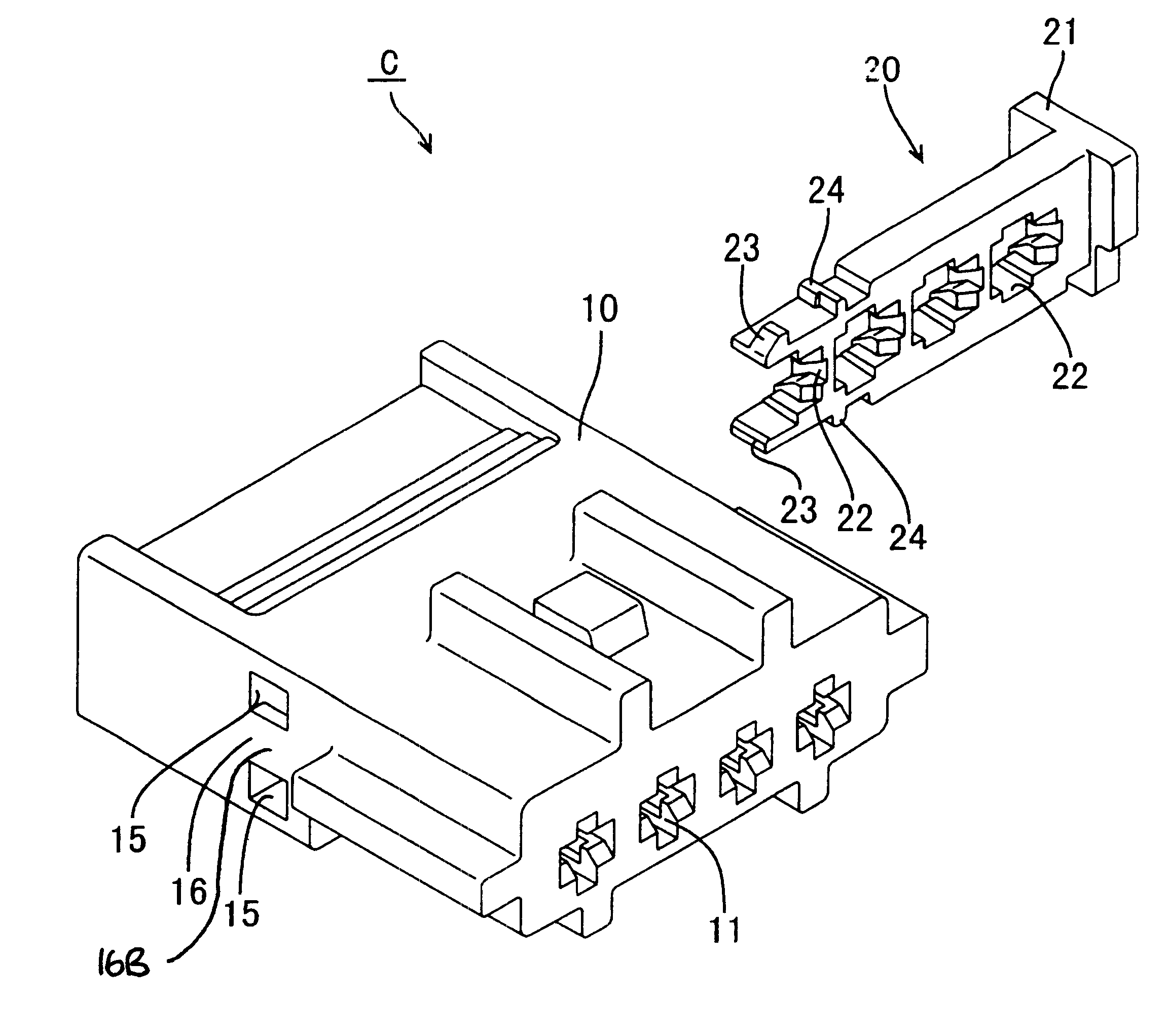
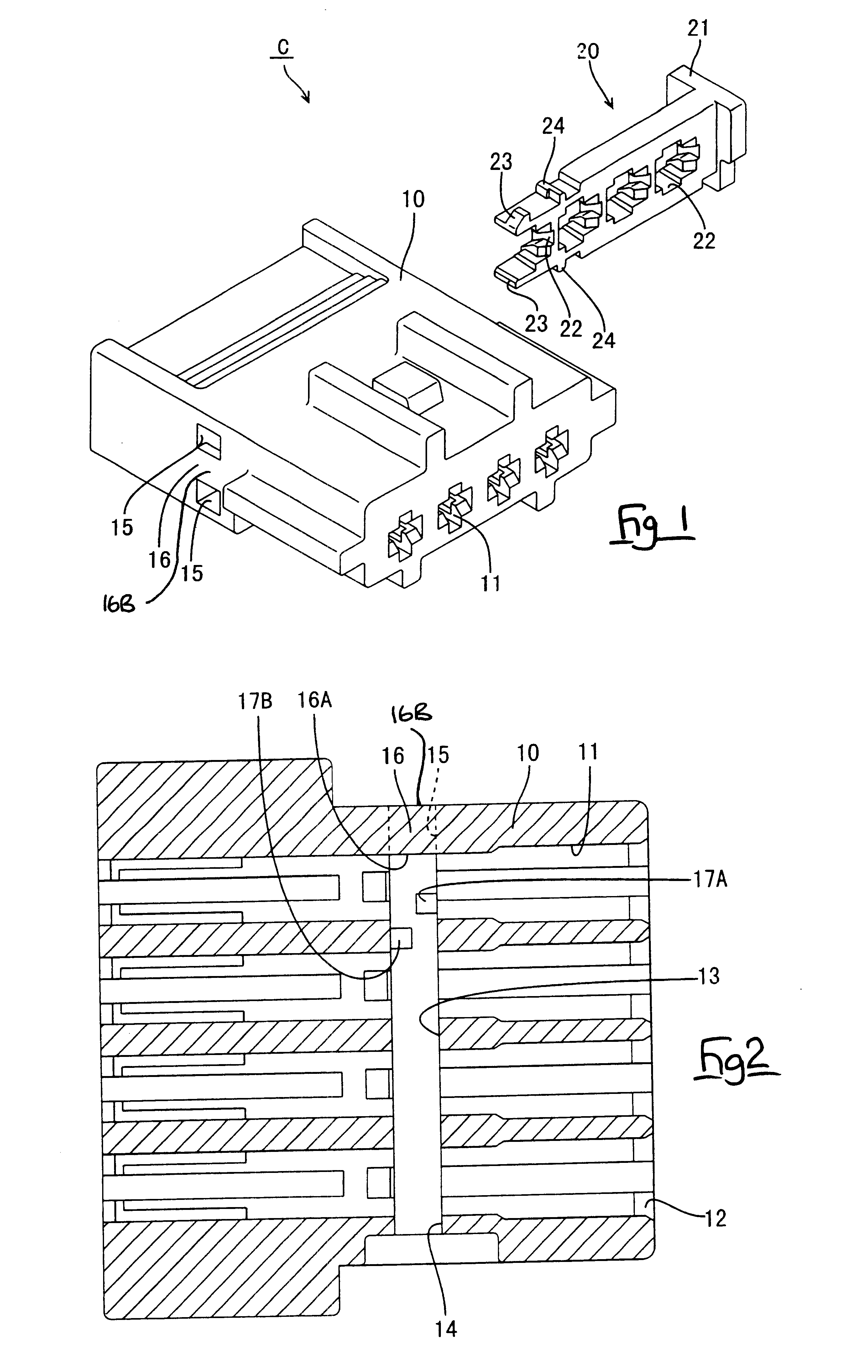
An embodiment of the present invention is described below with the aid of FIGS. 1 to 11.

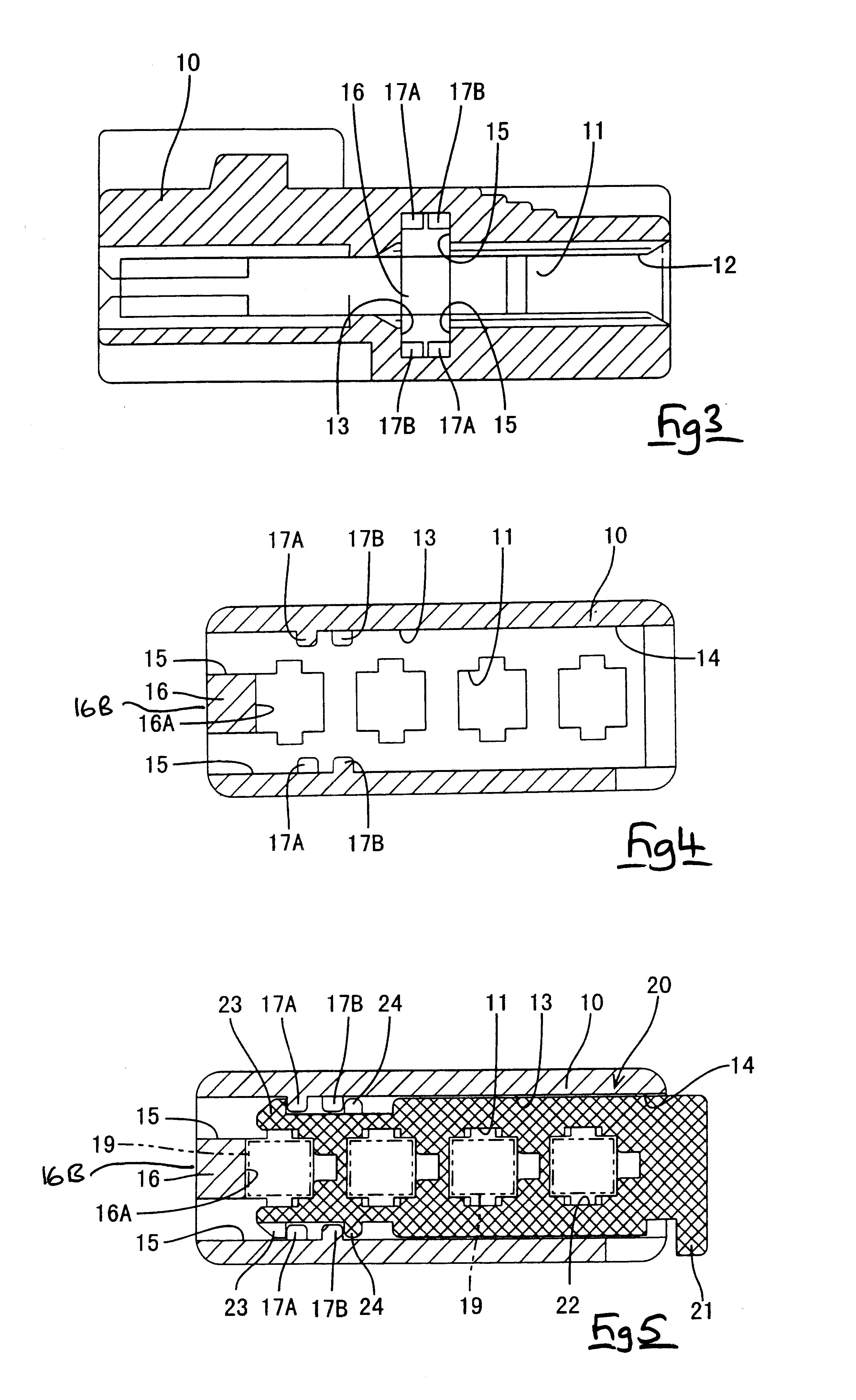
A connector C consists of a plastic housing 10, a plurality of terminal fittings 19 made from metal (although the present embodiment has four terminal fittings, there may be three or less, or five or more), and a plastic retainer 20. Corresponding cavities 11 are formed in a mutually aligned manner within the housing 10, and these cavities 11 open onto anterior and posterior side faces of the housing 10. The openings at the posterior side (the right side in FIGS. 2 and 3) form terminal fitting insertion holes 12 through which the terminal fittings 19 are inserted.

Left and right side faces (upper and lower side faces in FIG. 2, left and right side faces in FIGS. 4 to 6) of the housing 10 have openings therein which form a retainer attachment hole or retainer insertion cavity 13. This retainer attachment hole 13, when seen from a horizontal cross-sectional view, has a long, vertical slit shape. the...


PUM

PropertyMeasurementUnit
Strengthaaaaaaaaaa

Abstract

The invention provides a moulded plastic connector in which the mould is not weakened, and in which terminal fittings are not exposed. Portions of a side of a retainer attachment hole 13, which are opposite an insertion hole 14 for a retainer 20, are open to form mould removing holes 15, the remaining portion being covered by a wall 16. This wall 16 reduces the degree to which terminal fittings 19 are exposed from the interior of a housing 10. When a connector C is to be moulded, anterior ends of a first mould 30 (which is removed from the housing 10 via the insertion hole 14) and a second mould 40 (which is removed via the mould removing holes 15) fit together within the retainer attachment hole 13 in a doubled-over manner in a direction which intersects with the direction of mould removal. Consequently, the strength of the moulds 30 and 40 is not decreased.

Description

The present invention relates to a moulded electrical connector provided with a retainer, and a mould for manufacture of the connector.BACKGROUND TO THE INVENTIONA connector is provided with a side retainer for retaining terminal fittings, whereby the terminal fittings are inserted into a housing and the retainer is pushed in to intersect with these terminal fittings.This type of connector is described in JP 62-136781 and JP 1-197979.In this connector, if an attachment hole for the retainer is long and narrow or plate-shaped, a mould for forming this retainer attachment hole is also long and narrow or plate-shaped and may be relatively weak. Consequently, measures to strengthen it are required.One means of strengthening is to provide two moulds which have protruding moulding members whose protruding length is less than the depth of the retainer attachment hole. These protruding moulding members make mutual contact and thereby form one retainer attachment hole. In this case, the two ...

Claims


Application Information

Patent Timeline
IPC IPC(8): H01R43/24H01R43/20B29C33/42H01R43/00H01R13/42
CPCH01R43/24
Inventor SAKA, YUKINORICHISHIMA, MASAMITSU
Owner SUMITOMO WIRING SYST LTD
Why Eureka
Try Eureka