Unlock instant, AI-driven research and patent intelligence for your innovation.

Calender roll and process for operating a calender roll

a technology of calender and roll, applied in the field of calender roll, can solve the problems of paper web rejection, paper web rejection, paper web other material rejection,

Inactive Publication Date: 2002-10-15
VOITH PATENT GMBH
View PDF13 Cites 6 Cited by
  • Summary
  • Abstract
  • Description
  • Claims
  • Application Information

AI Technical Summary

Benefits of technology

The active oscillation effectively reduces or eliminates the formation of bar rings by synchronizing and adjusting the oscillations across the roll's axial length, minimizing sound levels and thickness variations, thereby preventing rejections.

Problems solved by technology

However, the same problems occur with other material webs as well.
This bar ring appearance causes, on the one hand, an undesired lined pattern on the paper web.
A certain depth and intensity on these bar rings leads to rejections in the paper web.
These exciting forces can have many causes, for instance, inhomogeneities, anisotropies, or geometric faults.
Due to the multitude of possible forms of natural oscillations these resonance points are practically unavoidable in the construction.
In addition to the oscillations at the calender that can be observed at the roll jacket during operation, the roll jacket is caused to oscillate as well.
Frequently, this can only be achieved with difficulties in practical use.
This is due to the fact that many roll jackets are flexible to the extent that an impulse of an actuator positioned in the middle is not necessarily sufficient in order to make the correlating active oscillation reach to the edge strips of the roll.

Method used


Image

  • Calender roll and process for operating a calender roll
  • Calender roll and process for operating a calender roll
  • Calender roll and process for operating a calender roll

Examples


Embodiment Construction

The particulars shown herein are by way of example and for purposes of illustrative discussion of the embodiments of the present invention only and are presented in the cause of providing what is believed to be the most useful and readily understood description of the principles and conceptual aspects of the present invention. In this regard, no attempt is made to show structural details of the present invention in more detail than is necessary for the fundamental understanding of the present invention, the description taken with the drawings making apparent to those skilled in the art how the several forms of the present invention may be embodied in practice.

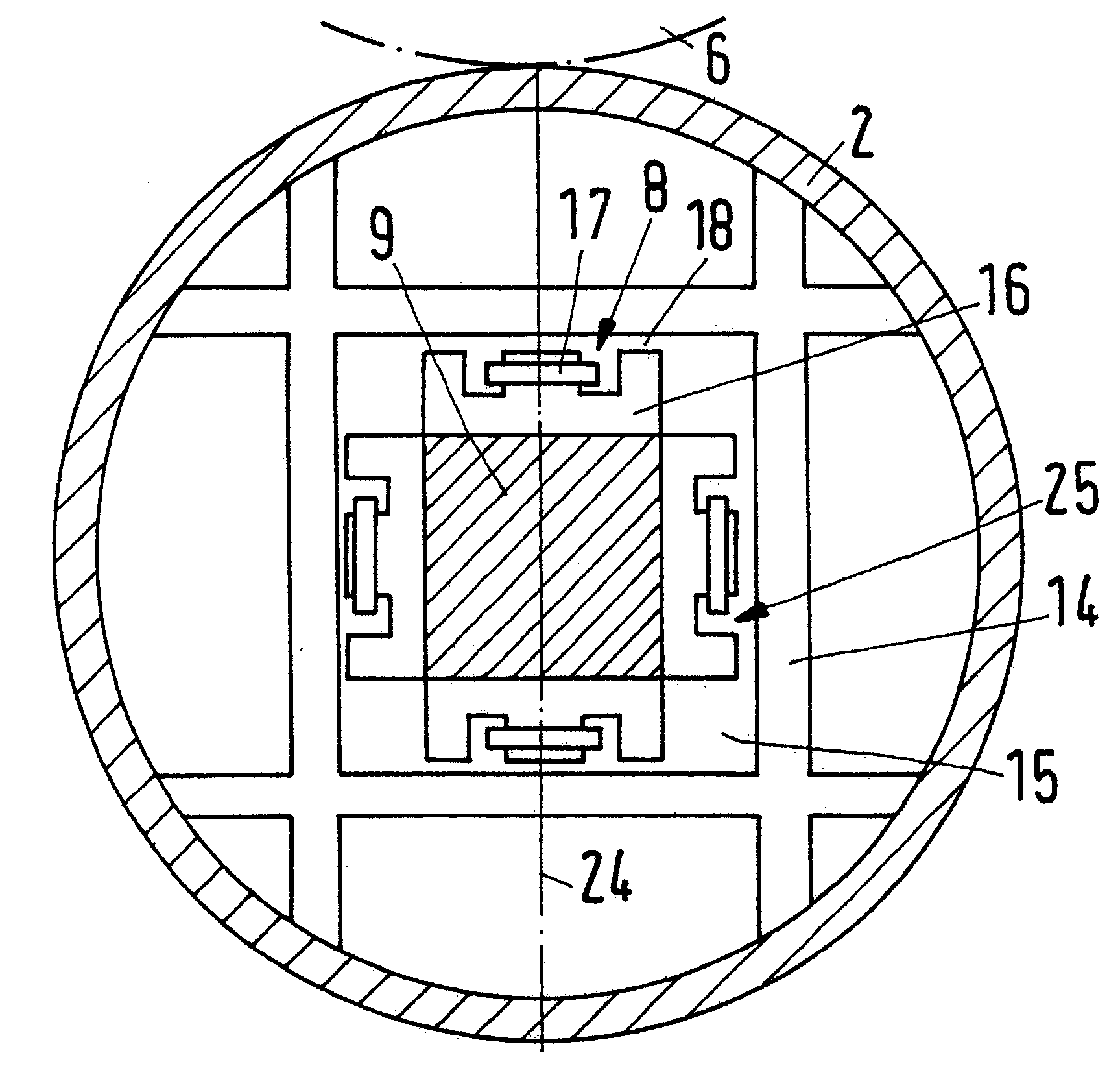
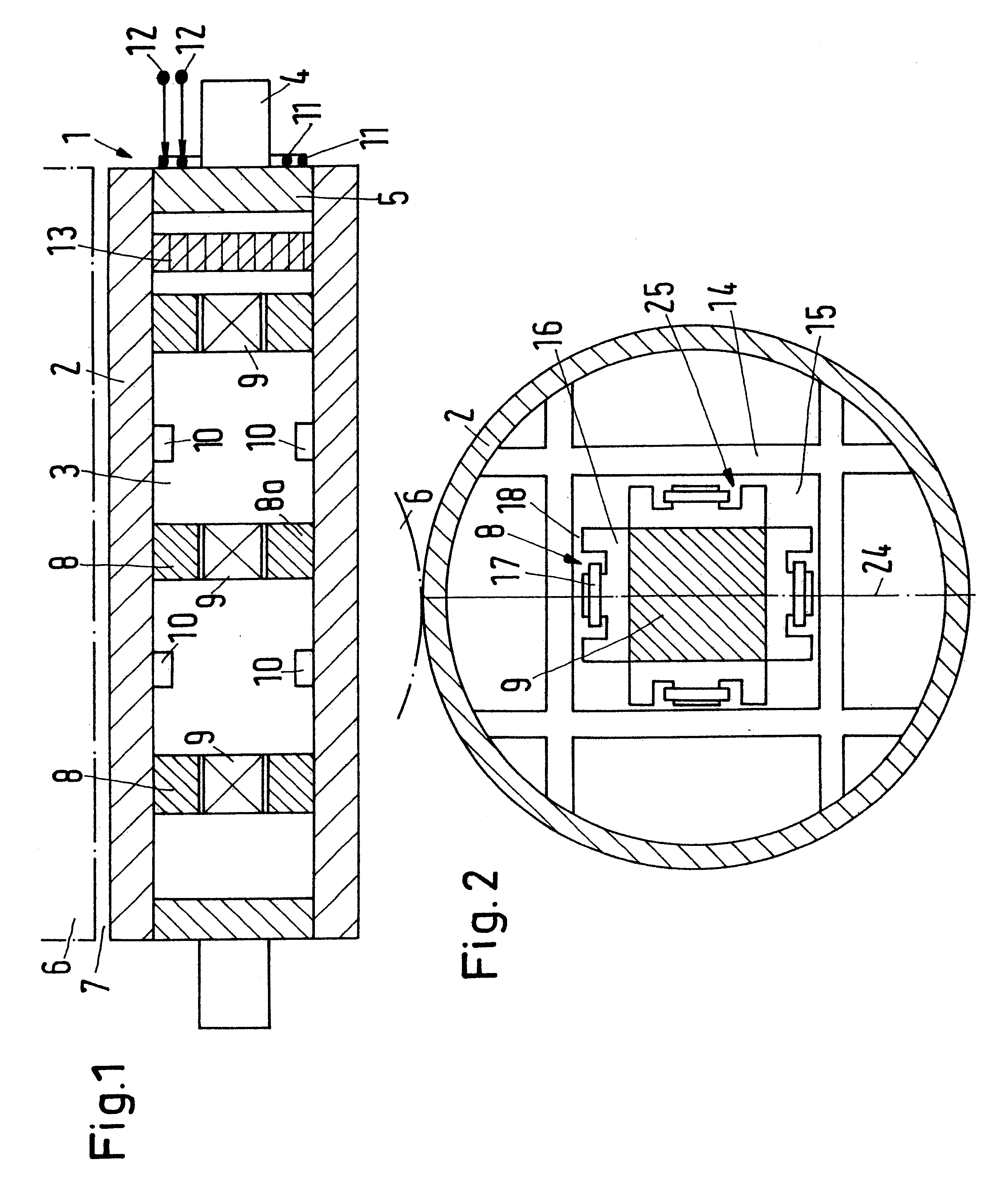
FIG. 1 depicts a lengthwise section through a calender roll 1 with a roll jacket 2 that surrounds an inner chamber 3. Further, the calender roll 1 is provided with roll pins 4 that are connected with pin discs 5 that seal the inner chamber 3 at the faces. The presence of roll pins 4 and pin discs 5, however, is not mandatory.

Th...


PUM


Abstract

A process is provided for operating a calender roll including a roll jacket surrounding an inner chamber. The process includes creating an active oscillation in the inner chamber that acts upon the roll jacket. By creating an oscillation within the calender roll, the appearance of undesired bar rings, which form on the external surface of the roll jacket due to operational exciting forces, is avoided. Furthermore, calender roll is provided including a roll jacket surrounding an inner chamber, and at least one actuator provided within said inner chamber acting upon said roll jacket.

Description

The present application claims priority under 35 U.S.C. .sctn. 119 of German Patent Application No. 100 08 800.7, filed on Feb. 25, 2000, the disclosure of which is expressly incorporated by reference herein in its entirety.1. Field of the InventionThe present invention relates to a calender roll having a roll jacket that surrounds an inner chamber. Furthermore, the invention relates to a process for operating the calender roll having a roll jacket that surrounds an inner chamber.2. Discussion of Background InformationSuch calender rolls are frequently used as center rolls in a calender, thus forming a part of a roll stack. Here, neighboring rolls form nips, through which a material web is guided in order to be exposed to an increased pressure or perhaps an increased temperature.Such rolls are widely used for the processing of a paper web which in the following is used as the example for describing the invention. However, the same problems occur with other material webs as well.In s...

Claims


Application Information

Patent Timeline
Patent Type & Authority Patents(United States)
IPC IPC(8): D21G1/00
CPCD21G1/008F16C13/024
Inventor KAYSER, FRANZKLAUI, ERICH
Owner VOITH PATENT GMBH