

Fermentation lock for wine barrel
a fermentation lock and wine barrel technology, applied in the field of seals and stoppers, can solve the problems of affecting the quality of production, and requiring the purchase and use of a second set of stoppers
- Summary
- Abstract
- Description
- Claims
- Application Information
AI Technical Summary
Problems solved by technology
Method used
Image

Examples
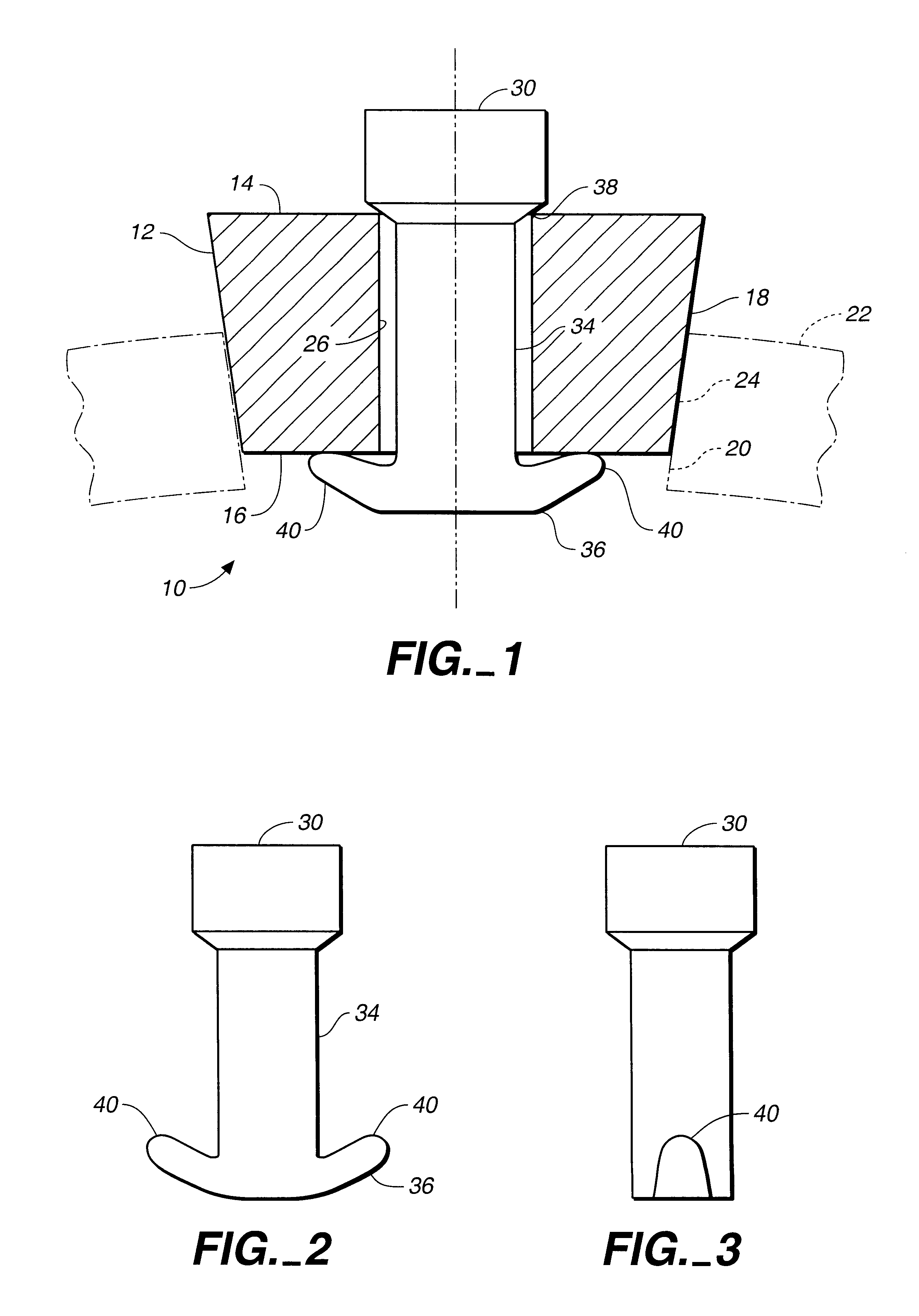
embodiment 50
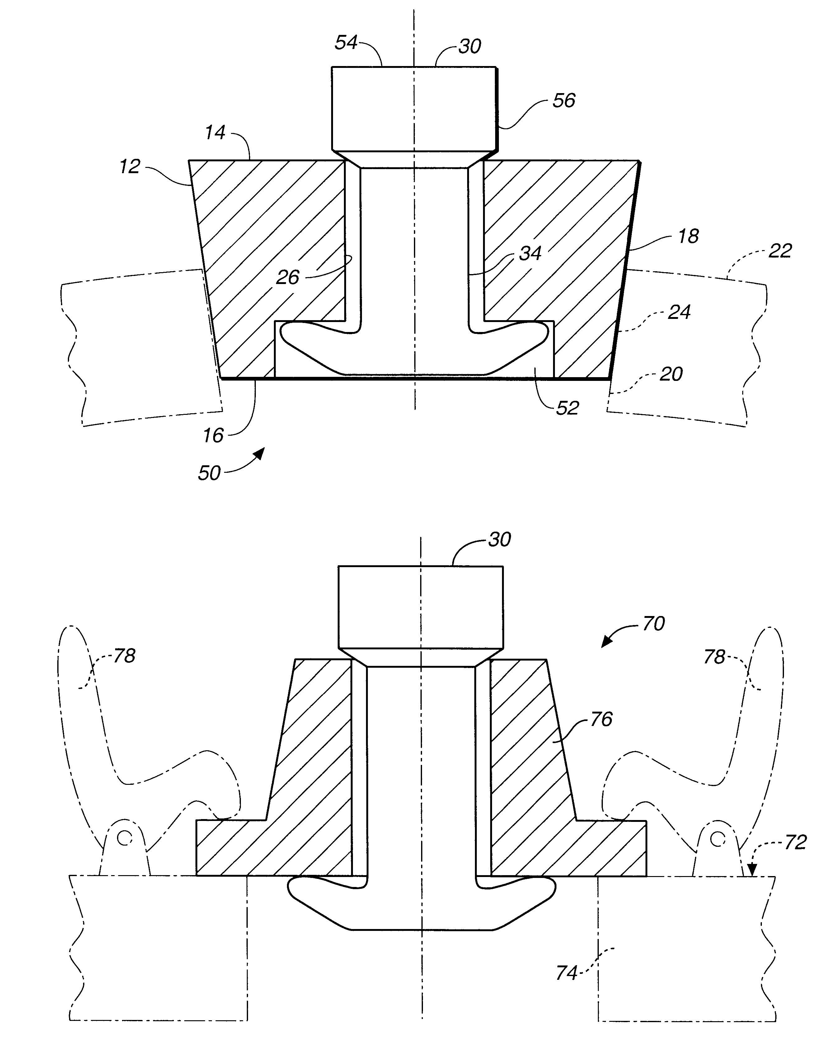
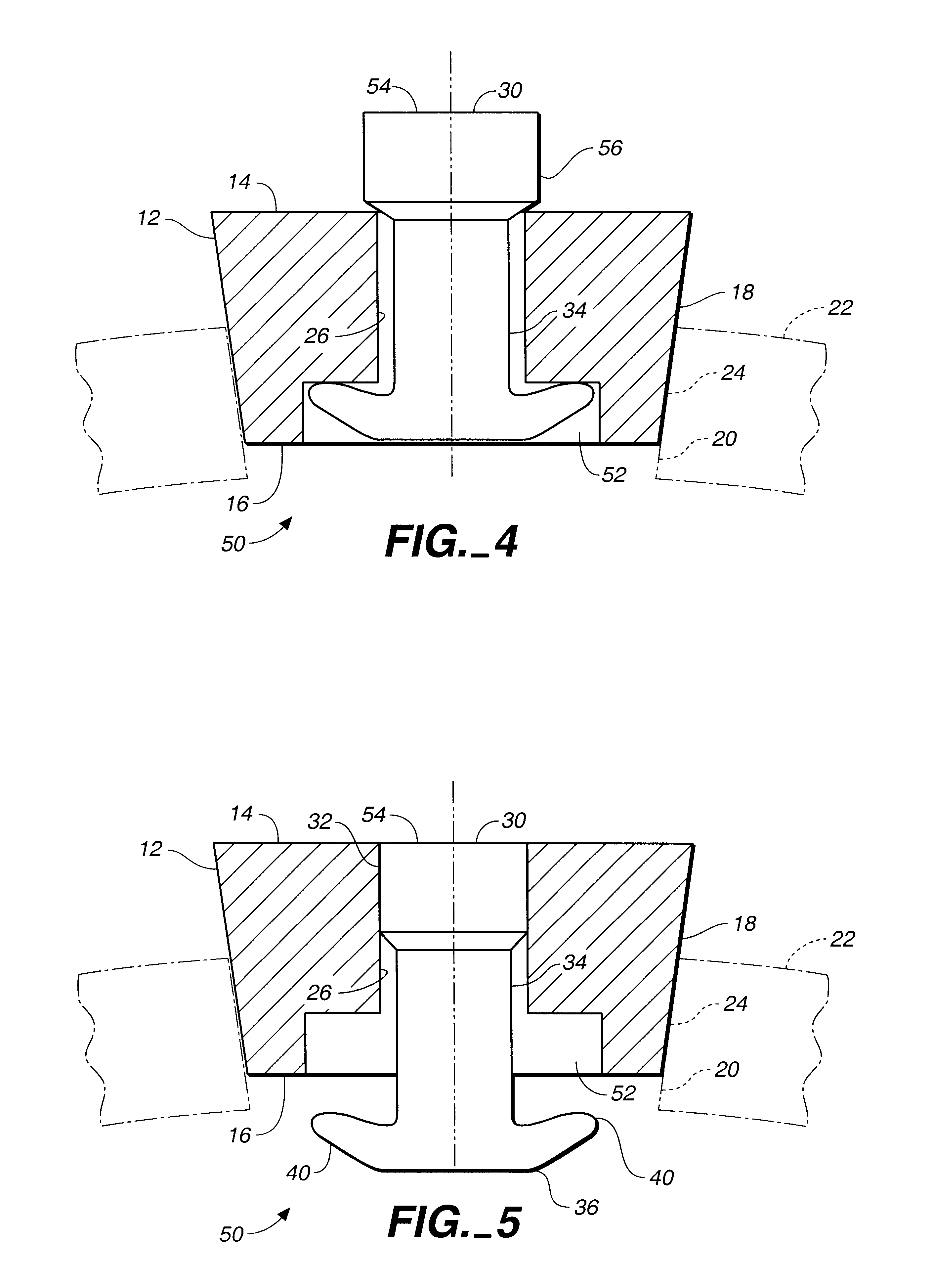
FIG. 4 is a side elevation cross-sectional view of a second preferred embodiment 50 of the present invention, wherein the bottom surface of the stopper member includes a recess 52 (shown in phantom) which fully accommodates the flexible lateral projections 40 of the sealing insert 30 member when the sealing insert member is functioning as a gas release during fermentation.
FIG. 5 is a side elevation cross-sectional view of the apparatus of FIG. 4, showing that the improved stopper apparatus of the present invention includes means for creating a seal between the exterior circumferential surface 56 of the top portion 32 of the sealing insert member 30 and the central aperture 26 of the stopper member 12. As illustrated in FIG. 5, the sealing insert member may thus be pushed down into the central aperture of the stopper member so as to form a positive seal so that the top surface 54 of the sealing insert member is flush with the top surface of the stopper member. This view also shows th...
embodiment 60
FIG. 6 is a cross-sectional side view in elevation of a second preferred embodiment 60 of the stopper of the present invention, while FIGS. 6A and 6B are upper and lower perspective views thereof. These views show that the stopper may take a shape other than frusto-conical and may include a threaded lower portion 62 for threading into a complementary threaded vessel hole 64. Accordingly, the stopper need not be restricted in its application to vessels adapted for a friction fit.
embodiment 70
FIG. 7 is a cross-sectional side view in elevation of a third preferred embodiment 70 of the stopper of the present invention, while FIGS. 7A and 7B are upper and lower perspective views, respectively, thereof. These views depict an embodiment suited for clamping engagement with the outer surface 72 of a vessel 74. The stopper includes a relatively thin lower rim 76 suited for securely clamping the stopper to the vessel surface by clamps 78.
It is contemplated that the second and third embodiments of the improved fermentation lock of the present invention would be fabricated of harder materials than those from which the first embodiment is fabricated, though the particular material characteristics may be adapted to the specific use to which the device will be put. In function and effect, however, the second and third embodiments duplicate the first embodiment.
PUM
 Abstract
Description
Claims
Application Information