Foldable stand

a stand and folding technology, applied in the field of stand, can solve the problems of large space required for transporting or storing the conventional stand, and the conventional stand is not foldabl

Inactive Publication Date: 2002-12-17
PAI LUCAS
View PDF4 Cites 39 Cited by
  • Summary
  • Abstract
  • Description
  • Claims
  • Application Information

AI Technical Summary

Problems solved by technology

Consequently, the conventional stand is not foldable.
A large space is required to transport or to store the conventional stand.

Method used


Image

  • Foldable stand
  • Foldable stand
  • Foldable stand

Examples


Embodiment Construction

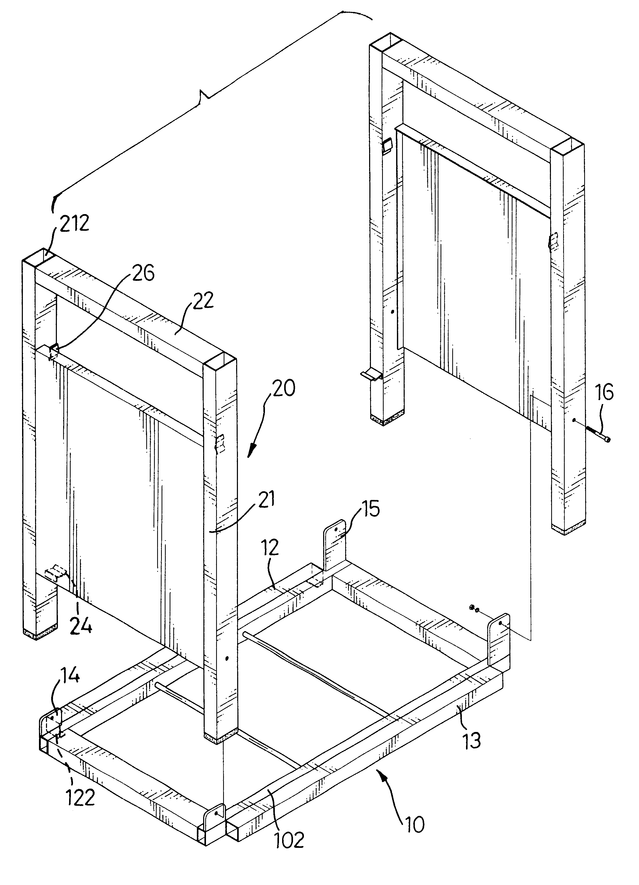
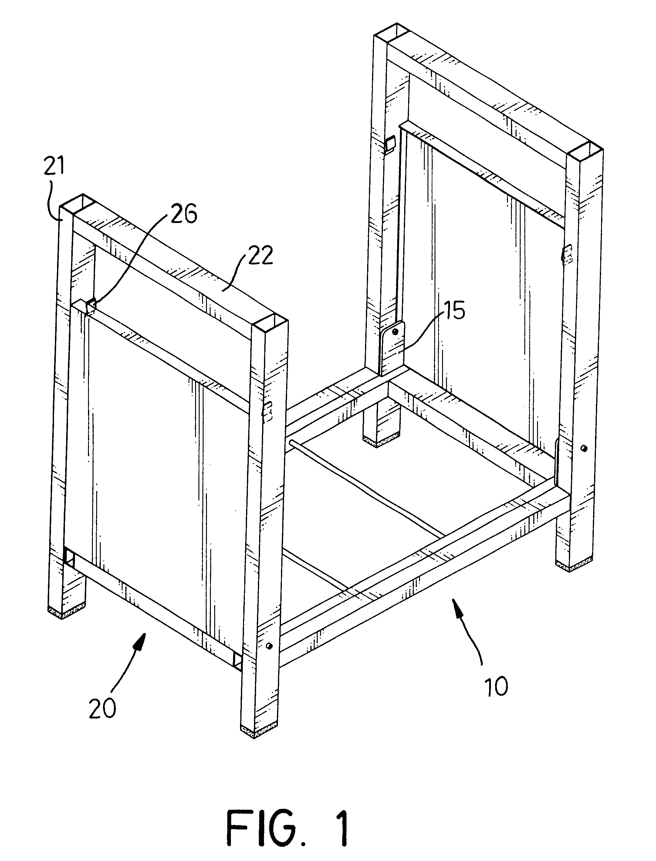
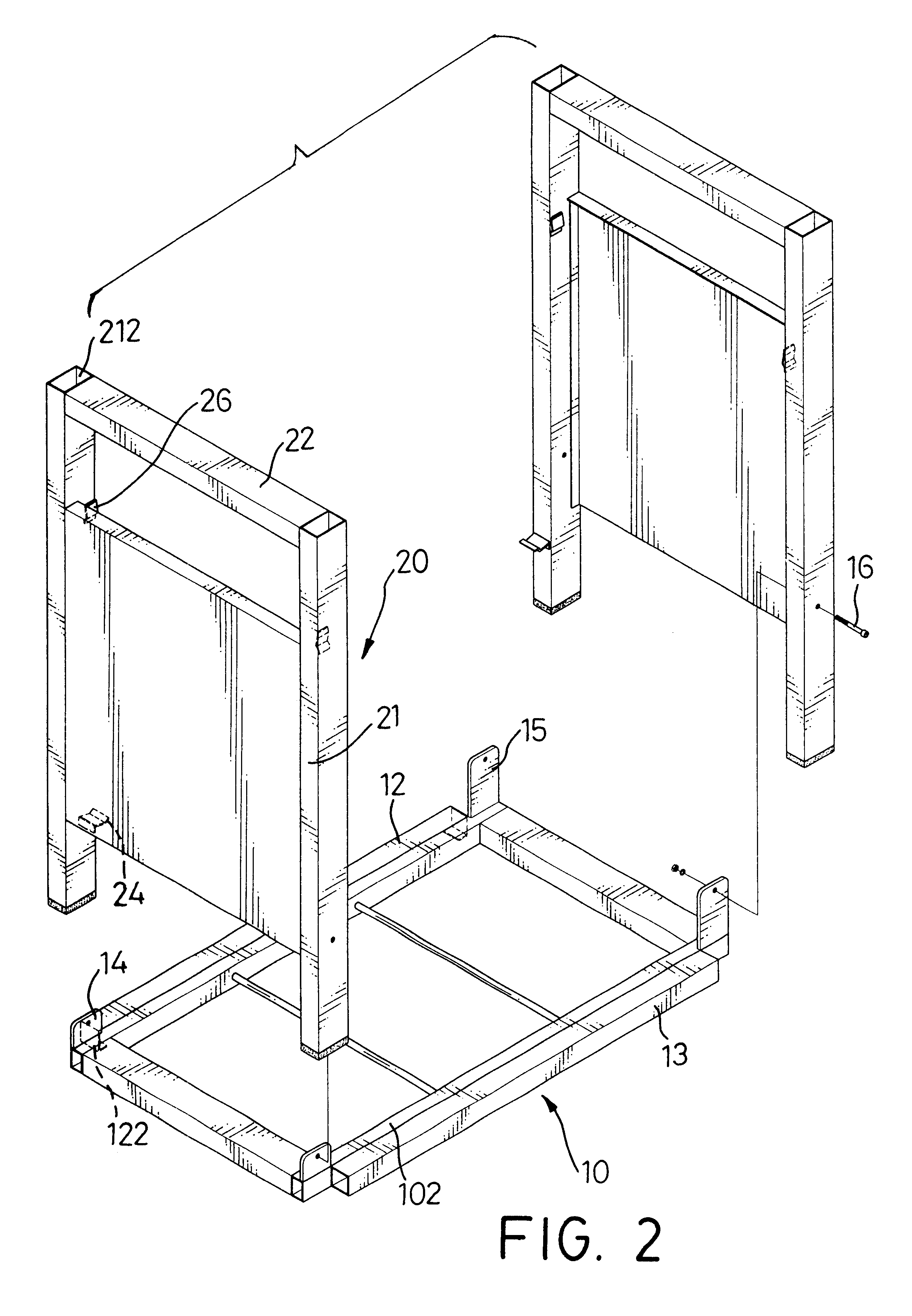
With reference to FIGS. 1 and 2, a stand in accordance with the present invention comprises a bottom frame (10) and two side frames (20). Each frame (10, 20) is comprised of multiple tubular members. The bottom frame (IO) is comprised of four tubular members assembled in a rectangle. The side frames (20) have similar structures. Each side frame (20) is comprised of two longitudinal tubular members (21) with a top and a bottom end and a lateral tubular member (22) secured between the top ends of the longitudinal tubular member (21) to form an inverse U-shaped frame. The side frames (20) are respectively pivotally attached to opposite ends of the bottom frame (10). A first pivotal plate (14) extends upward from each side of one end of the bottom frame (10), and a second pivotal plate (15) extends upward,from each side of the other end of the bottom frame (10). Each second pivotal plate (15) is longer than each first pivotal plate (14). One of the side frames (20) is pivotally connecte...


PUM


Abstract

A stand to support an object has a bottom frame and two side frames. The side frames are each pivotally attached to opposite ends of the bottom frame with a pair of pivot pins. The pairs of pivot pins are located at different heights. A clasp is mounted on each side frame to detachably engage the bottom frame. When the clasps are released from the bottom frame, the side frames can be pivoted relative to the bottom frame. The stand is foldable. Because the side frames are respectively pivotally attached to the bottom frame by pairs of pivot pins at different heights, one of the side frames can overlap the other side frame. The size of the stand is reduced. Transporting and storing the stand become more convenient.

Description

1. Field of the InventionThe present invention relates to a stand, and more particularly to a foldable stand to support a barbecue grill, a water basin or the like.2. Description of Related ArtA stand supports an object like a barbecue grill, a water basin or the like to elevate the object to a position where the user can easily use the object. A conventional stand to support an object is a fixed structure and is composed of multiple members attached to each other by permanent or semi-permanent fasteners like bolts or rivets. Consequently, the conventional stand is not foldable. A large space is required to transport or to store the conventional stand.To overcome the shortcomings, the present invention provides a foldable stand to mitigate or obviate the aforementioned problems.The main objective of the invention is to provide a stand to support an object and which is foldable. The stand has a bottom frame and two side frames. The side frames are each pivotally attached to opposite ...

Claims


Application Information

Patent Timeline
Patent Type & Authority Patents(United States)
IPC IPC(8): A45D19/04A45D19/00F16M11/00
CPCA45D19/04F16M11/00F16M11/38A47J2037/0777
Inventor PAI, LUCAS
Owner PAI LUCAS
Why Eureka
Try Eureka