Piezoelectric wave motor

a wave motor and piezoelectric technology, applied in piezoelectric/electrostrictive/magnetostrictive devices, piezoelectric/electrostriction/magnetostriction machines, electrical equipment, etc., can solve problems such as motor failure, motor reliability decline, and crack growth within the elements

Inactive Publication Date: 2003-02-11
HONEYWELL FED MFG & TECHNOLOGI
View PDF25 Cites 10 Cited by
  • Summary
  • Abstract
  • Description
  • Claims
  • Application Information

AI Technical Summary

Benefits of technology

In order to address these objects, the present invention utilizes a series of slots formed in the stator transverse to the desired wave motion. Piezoelectric elements are contained within these slots. Upon imposing an appropriate electric field, the elements deform, exerting forces perpendicular to the sides of the slots (i.e., in the direction of the desired wave motion). Because the elements so mounted impart forces resulting from their deformation in a direction perpendicular to the surface of the slots, shear forces imposed upon the elements are minimized or eliminated.
In another preferred aspect, the piezoelectric elements contained in slots may be operated in the d.sub.33 mode. Operation in this mode maximizes the deformation achieved from an element for a given electric field, thus maximizing relative motion of the stator.
In a further preferred aspect, the individual piezoelectric elements contained in slots are stacked together to form what will be referred to as piezoelectric stacks. As the term is used herein, a piezoelectric stack consists of a plurality of piezoelectric elements mechanically connected side-to-side, with the elements being poled and electrically connected so that when an electric field is imposed, the deformation of the stacked elements is additive. Stacking may readily be accomplished where the elements are operated in the d.sub.33 mode so that contiguous portions of adjacent elements may be electrically connected (operated at the same potential).

Problems solved by technology

Because piezoelectric elements are ceramics, and are typically weak in tension these alternating tension stresses promote the growth of cracks within the elements.
Over time, these cracks will decrease motor reliability and may eventually lead to the failure of motor 10.
Thus, motor 10 does not fully utilize the piezoelectric properties of the elements.
Thus, for example, the levers could be constructed of a lighter and stronger material than the stator, wherein the lever material requires a relatively high-temperature manufacturing process, and should one of the levers fail it alone may be quickly replaced rather than laboriously and inefficiently replacing the entire stator / lever unit.

Method used


Image

  • Piezoelectric wave motor
  • Piezoelectric wave motor
  • Piezoelectric wave motor

Examples


Embodiment Construction

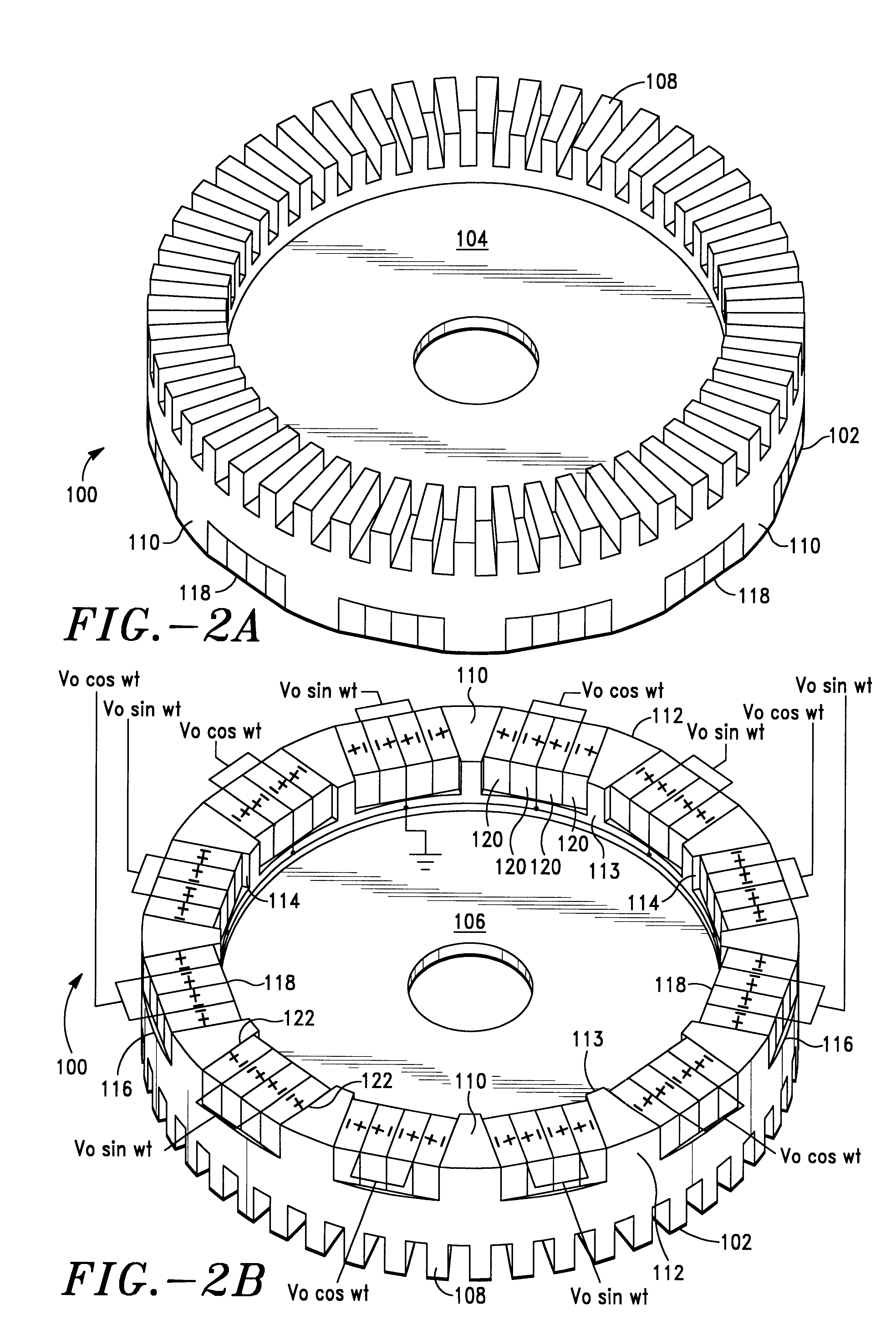
Referring to FIGS. 2A and 2B, an embodiment of the stator-piezoelectric stack assembly is designated generally as reference numeral 100, wherein FIG. 2A illustrates assembly 100 in its original upright position and FIG. 2B illustrates assembly 100 in an inverted position.

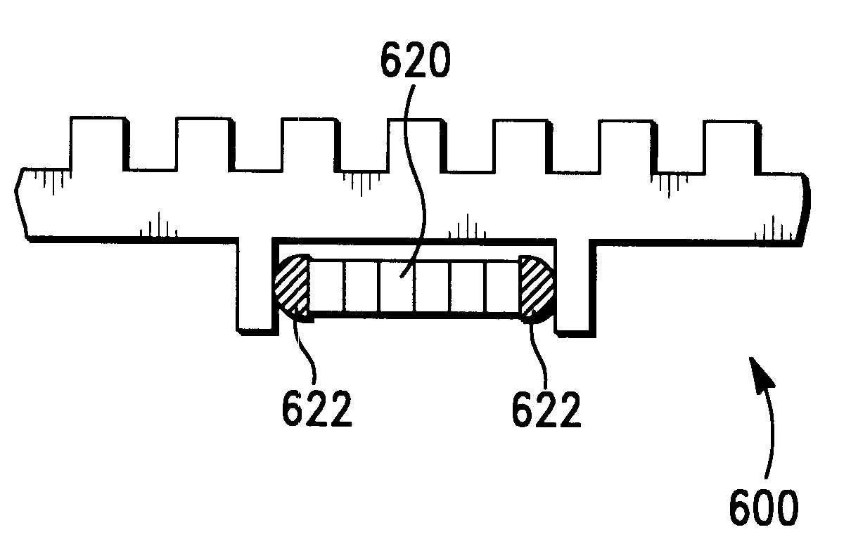
Assembly 100 includes a disk-shaped stator 102 having a generally circular top surface 104 (see FIG. 2A) and a generally circular bottom surface 106 (see FIG. 2B). Cut into top surface 104 of stator 102 are a plurality of comb-like teeth 108 which are uniformly dispersed around and extend upwardly from the periphery of top surface 104. As is known in the art, teeth 108 function to amplify the traveling wave generated in stator 102 during the operation of the piezoelectric motor. Similarly, projecting from the bottom surface 106 of stator 102 are a plurality of levers 110 which are uniformly dispersed around and extend downwardly from the periphery of bottom surface 106. In this embodiment, levers 110 taper inwardly ...


PUM


Abstract

A piezoelectric motor having a stator in which piezoelectric elements are contained in slots formed in the stator transverse to the desired wave motion. When an electric field is imposed on the elements, deformation of the elements imposes a force perpendicular to the sides of the slot, deforming the stator. Appropriate frequency and phase-shifting of the electric field will produce a wave in the stator and motion in a rotor. In a preferred aspect, the piezoelectric elements are configured so that deformation of the elements in the direction of an imposed electric field, generally referred to as the d33 direction, is utilized to produce wave motion in the stator. In a further aspect, the elements are compressed into the slots so as to minimize tensile stresses on the elements in use.

Description

1. Field of the InventionThe present invention relates to piezoelectric motors. More particularly, the present invention relates to a unique configuration for mounting piezoelectric elements in a piezoelectric wave motor.2. Description of Related ArtPiezoelectric motors are utilized in a wide variety of applications in modern society, such as autofocusing camera lenses and automatic control units for window blinds. Piezoelectric motors are particularly well-suited for any application which requires a motor having a compact size (e.g. as small as the size of a fingertip), quiet operation, high torques at low speeds, quick response, and which is not affected by magnetic fields.A typical design of an existing piezoelectric motor is shown in FIG. 1 designated by reference numeral 10. Motor 10 is a rotary motor that includes a disk-shaped stator 12 having a comb-tooth top surface 14 and flat bottom surface 16. Motor 10 also includes a thin piezoelectric ring 18, which is bonded to bottom...

Claims


Application Information

Patent Timeline
Patent Type & Authority Patents(United States)
IPC IPC(8): H01L41/09H02N2/00H02N2/08H02N2/12H02N2/16
CPCH02N2/163
Inventor YERGANIAN, SIMON SCOTT
Owner HONEYWELL FED MFG & TECHNOLOGI
Why Eureka
Try Eureka