Achromatic retarder array for polarization imaging

a retarder array and polarization imaging technology, applied in the field of optical components, can solve the problems of inability to develop a practical and reliable method of imaging circular polarization, introduce weight and cost, and reduce the reliability of sensors

Inactive Publication Date: 2003-05-13
CHUN CORNELL SEU LUN
View PDF9 Cites 57 Cited by
  • Summary
  • Abstract
  • Description
  • Claims
  • Application Information

AI Technical Summary

Problems solved by technology

However, a practical and reliable method of imaging circular polarization has not been developed.
In a circular polarization sensor, the mechanism for rotating the linear polarizer or retarder introduces weight and cost and makes the sensor less reliable.
In addition, the frequency at which the images can be updated, i.e. the frame rate, is limited by the rotation rate.
However, quarter-wave retarders with suitable characteristics have not been developed.
However,

Method used


Image

  • Achromatic retarder array for polarization imaging
  • Achromatic retarder array for polarization imaging
  • Achromatic retarder array for polarization imaging

Examples


Embodiment Construction

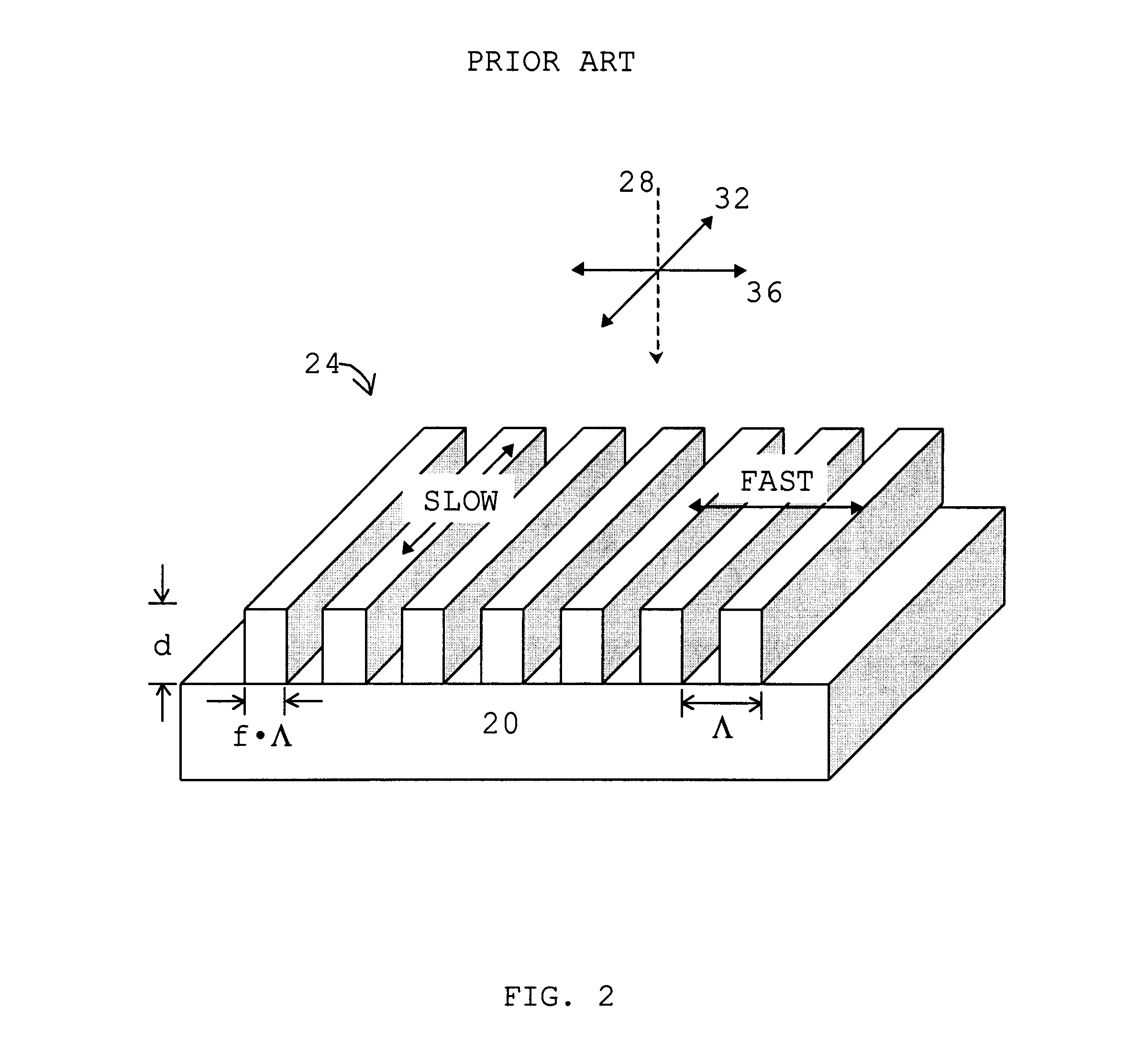
FIG. 2. Shows a typical surface-relief grating which can be used as a waveplate. A substrate 20 is a material which is transparent to light and has index of refraction n. Substrate 20 has a planar surface on which a surface-relief grating 24 is formed. Surface-relief grating 24 is a series of linear ridges, of rectangular profile, arranged parallel to each other and equally spaced. The period of the ridges is .LAMBDA.. The width of a ridge is f.multidot..LAMBDA.. The height, or thickness, of the ridges is d.

The behavior of grating 24 as a waveplate can be described as follows. Light 28 is traveling in a direction normal to the planar surface and is incident on grating 24. If the wavelength of light 28 is greater than .LAMBDA..multidot.n, then the light will not be diffracted by grating 24, and grating 24 is a birefringent material. The electric vector of light 28 has two states of oscillation, a state of oscillations along a direction 32 parallel to the linear ridges and a state of ...


PUM


Abstract

In addition to having color, light waves have the attribute of polarization. An apparatus and method to convert circular polarized light into linearly polarized light over a wide range of wavelengths is provided by utilizing a first surface-relief grating functioning as a quarter-wave waveplate and a second surface-relief grating functioning as a half-wave waveplate. A plurality of such devices are arranged in a two-dimensional array and combined with an array of linear polarizers and an array of photodetectors to form a polarization imaging sensor. Such a sensor could have applications in automobiles to alert drivers of the presence of other vehicles, especially at night, in fog, or in rain. Military applications include the detection of vehicles placed among trees and shrubs. Another advantage of using circular polarization images is that the sign and magnitude of the circular polarization can potentially be used to reveal the spatial orientation, material, and surface roughness of the object's surface.

Description

BACKGROUND--FIELD OF INVENTIONThe invention relates to optical components particularly with respect to controlling the polarization of optical radiation.BACKGROUND--DESCRIPTION OF THE PRIOR ARTIn addition to having color, light waves have the attribute of polarization. Light is a superposition of two orthogonal states of polarization. We can consider one of these states to be an oscillation of the wave up and down along a vertical direction. The other state will be an oscillation left and right along a horizontal direction. If the two states are oscillating in phase, then, at a given point in space, the electric field vector of the light wave traces, in time, a segment along a straight line. The light is said to be linearly polarized. When the two states are oscillating partially out of phase, then the electric vector traces an ellipse. In particular, when they are out of phase by 90 degrees and the oscillation amplitudes are equal, then the electric vector traces a circle, and the ...

Claims


Application Information

Patent Timeline
IPC IPC(8): G02B5/30G02B5/18
CPCG02B5/1814G01J4/04G02B5/3083
Inventor CHUN, CORNELL SEU LUN
Owner CHUN CORNELL SEU LUN
Why Eureka
Try Eureka