Device for displacing to nozzle outlet or eliminating jet separation in rocket engine nozzles, and a nozzle including the device

a technology for rocket engines and nozzles, which is applied in the direction of machines/engines, vessel construction, marine propulsion, etc., can solve the problems of affecting the structure of the diverging portion, affecting reducing the flow rate of the rocket engine, so as to reduce eliminate or reduce the effect of jet separation in the nozzle and control the phenomenon of jet separation

Inactive Publication Date: 2003-06-03
SN DETUDE & DE CONSTR DE MOTEURS DAVIATION S N E C M A
View PDF11 Cites 5 Cited by
  • Summary
  • Abstract
  • Description
  • Claims
  • Application Information

AI Technical Summary

Benefits of technology

The invention seeks to remedy the above drawbacks and to provide a device enabling jet separation in a nozzle to be eliminated or reduced. The invention seeks to reduce and control the phenomenon of jet separation by means of a device which is passive and does not consume fluid, whether for cooling purposes or for jet control purposes, and which presents structure that is static, thereby guaranteeing that the device is simple and reliable.
In this way, any leaks between the device and the outside wall of the nozzle can be limited.

Problems solved by technology

Consequently, at atmospheric pressure as it exists at sea level, the expansion of gases in the nozzle is limited by the phenomenon of the jet separating from the wall of the diverging portion of the nozzle.
A drawback of the jet separating inside the nozzle is to create mechanical forces in the separation zones that are harmful to the structure of the diverging portion.
Those fragile and bulky systems are not designed to be jettisoned at the matched altitude and they are therefore difficult to apply to the main thrust nozzles of a rocket.
Nevertheless, such a system is complex and runs the risk of damaging the diverging portions as successive parts are jettisoned.
Furthermore, sealing between the ejectable diverging portions is a major problem since the gases tend to filter between said elements and to damage them on their outside faces which are not designed to be subjected to hot gases.
A difficulty encountered by that device is the thermal behavior of the ejectable element, which is not provided with cooling and which is subjected to temperatures close to those of the gases in the combustion chamber, i.e. about 3000 kelvins (K).
That leads to problems of fluid consumption and of reliability in operation.
That system is constituted by multiple moving elements (e.g. valves) difficult to make reliable in operation in the sound and vibration environment of a rocket engine.
Furthermore, like the system described in document U.S. Pat. No. 5,450,720 which shows a nozzle in which separation is controlled by admitting ambient air through large longitudinal slots formed in the wall of the nozzle, that system of U.S. Pat. No. 5,683,033 for admitting ambient air suffers from the risk of additional combustion of the gases coming from the nozzle, with the consequence of heating taking place at the wall of the diverging portion, thereby likewise requiring special thermal protection.
Those fluid injection devices nevertheless require complex valve and control equipment for controlling flow rate, which leads to a considerable increase in the weight of the diverging portion of the nozzle.
Furthermore, since those devices consume fluid, they are of use only when a gas is available at low cost and of little use otherwise, i.e. only with bypass flow engines.
In addition, that equipment is expensive, is necessarily heavy because of the presence of valves, and installing it at the bottom end of a nozzle gives rise to a large amount of nozzle inertia that is detrimental to the strength of the thrust chamber.

Method used


Image

  • Device for displacing to nozzle outlet or eliminating jet separation in rocket engine nozzles, and a nozzle including the device
  • Device for displacing to nozzle outlet or eliminating jet separation in rocket engine nozzles, and a nozzle including the device
  • Device for displacing to nozzle outlet or eliminating jet separation in rocket engine nozzles, and a nozzle including the device

Examples


Embodiment Construction

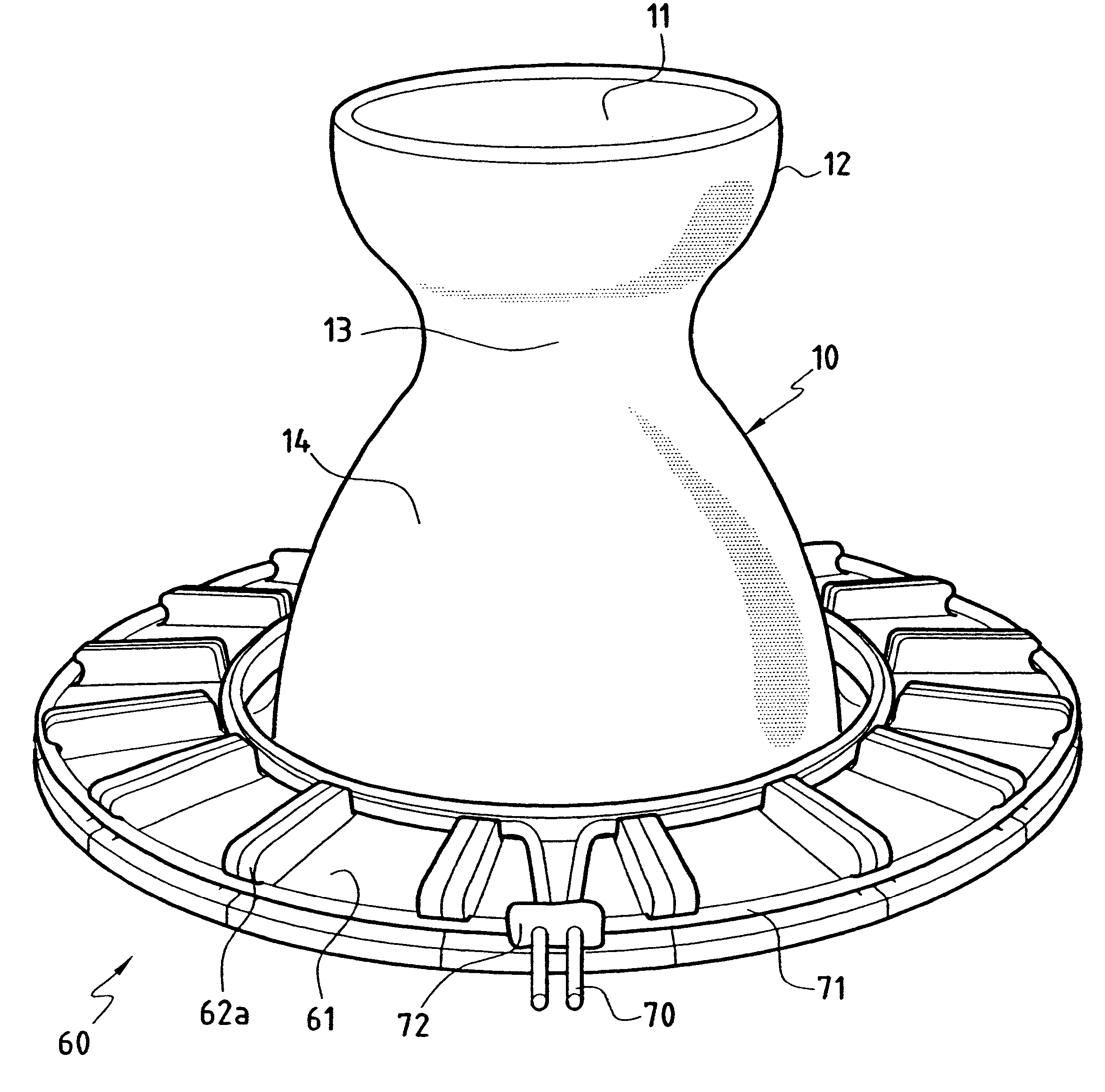
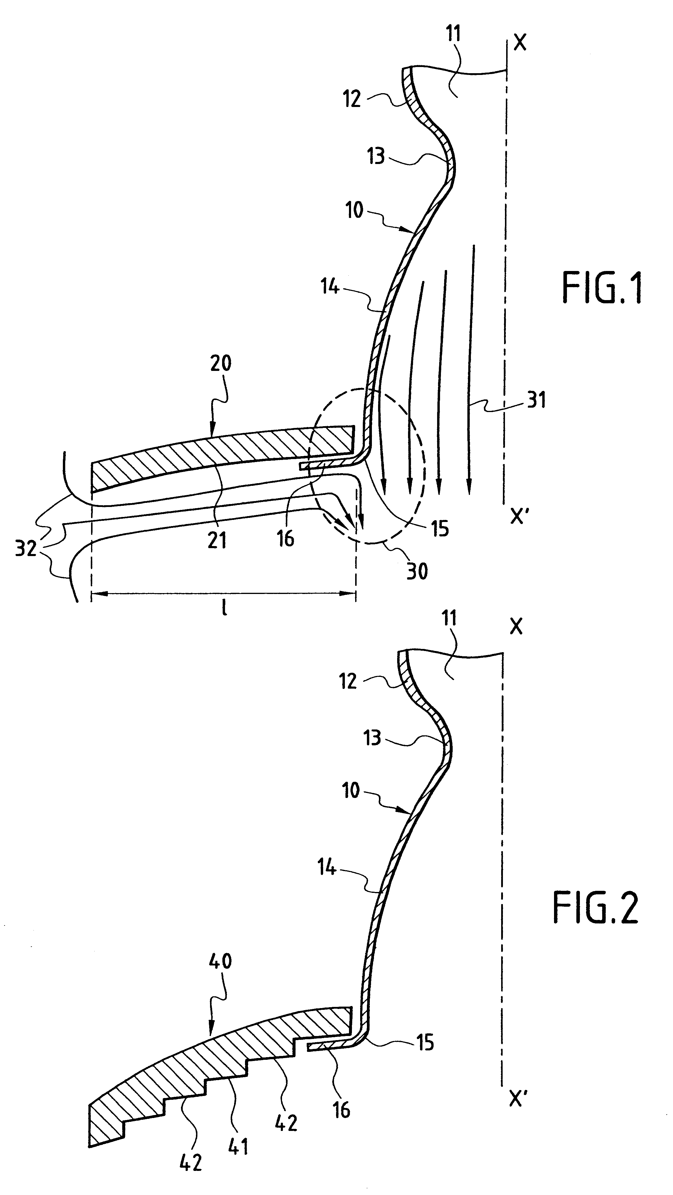
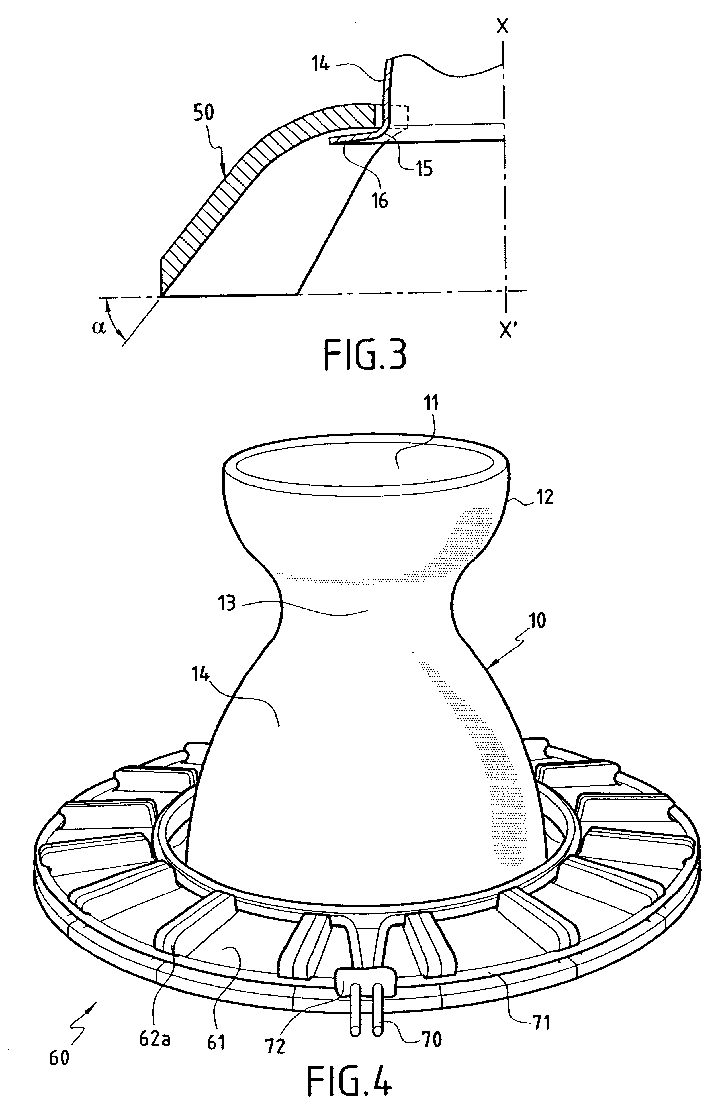
FIG. 1 is a general section view of a rocket engine nozzle 10 for operation with a device of the present invention. The nozzle 10 comprises an upstream converging portion 12 receiving the hot gases produced in a combustion chamber 11, a nozzle throat 13 of section area Sc, and a diverging portion 14 which expands the hot gases downstream from the throat 13 and ejects them from the downstream end 15 of the diverging portion which defines a nozzle outlet section of area Se.

When seeking to optimize rocket engine nozzles to create a high ejection speed for the hot gases produced in the chamber, it is necessary in particular to expand the gases as much as possible in the nozzle by adopting for this purpose a large ratio for the section defined by the outlet section area Se over the section area of the throat Sc. As already mentioned, for a given thruster operating at a given rate, a nozzle can be matched only for a single altitude which is generally situated at a height of several kilome...


PUM


Abstract

To control the separation of a hot gas ejection jet within a rocket engine nozzle, the device includes a jettisonable annular structure for placing around the outside wall of the nozzle at the gas cutlet section thereof, which structure defines a radial extension around the nozzle so that in the presence of an outlet jet coming from the nozzle, it creates a low pressure zone in the vicinity of the bottom face of the device, thereby displacing in the gas outlet direction jet separation from the interior wall of the nozzle.

Description

The invention relates to a device for controlling jet separation for rocket engine nozzles having a large section ratio and intended for operation under conditions of varying pressure.PRIOR ARTTo obtain high specific impulse at altitude, rocket engines are fitted with nozzles having a large section ratio. For a given engine, as it rises through the atmosphere, ambient pressure drops off, passing from atmospheric pressure at sea level to a low pressure that is a function of altitude. Nozzles are generally optimized as a function of the overall performance of a launcher, which leads to using nozzles that are overexpanded so as to provide maximum thrust at a "matched" altitude. Consequently, at atmospheric pressure as it exists at sea level, the expansion of gases in the nozzle is limited by the phenomenon of the jet separating from the wall of the diverging portion of the nozzle.That phenomenon exists throughout an initial stage of flight that starts at liftoff and continues up to the...

Claims


Application Information

Patent Timeline
Patent Type & Authority Patents(United States)
IPC IPC(8): F02K9/97F02K9/00
CPCF02K9/978
Inventor VUILLAMY, DIDIERHARLAY, JEAN-CLAUDE
Owner SN DETUDE & DE CONSTR DE MOTEURS DAVIATION S N E C M A
Why Eureka
Try Eureka