Metal shears with an attached tag

a metal shear and tag technology, applied in the field of metal shears with attached tags, can solve the problems of distortion of what is being seen, the inability to clearly show the information or instructions on the conventional metal shear to the buyer or the user, and the difficulty of marking information or instructions on the metal shears

Inactive Publication Date: 2003-06-10
HUANG HSIN TE
View PDF5 Cites 50 Cited by
  • Summary
  • Abstract
  • Description
  • Claims
  • Application Information

AI Technical Summary

Problems solved by technology

However, because the conventional metal shears are made of metal, it is very difficult to mark information or instructions about the shears onto the metal shears.
The marks on the conventional metal shears cannot clearly show the information to the buyer or the user.
Despite the cover being substantially transparent, it is found that distortions occur in what is being viewed because the cover is made of pliable plastic.
Furthermore, the user must rotate by hand the conventional locking lever (38) and so to release the locking lever (38) from the third pivot pin (37) is inconvenient.

Method used


Image

  • Metal shears with an attached tag
  • Metal shears with an attached tag
  • Metal shears with an attached tag

Examples


Embodiment Construction

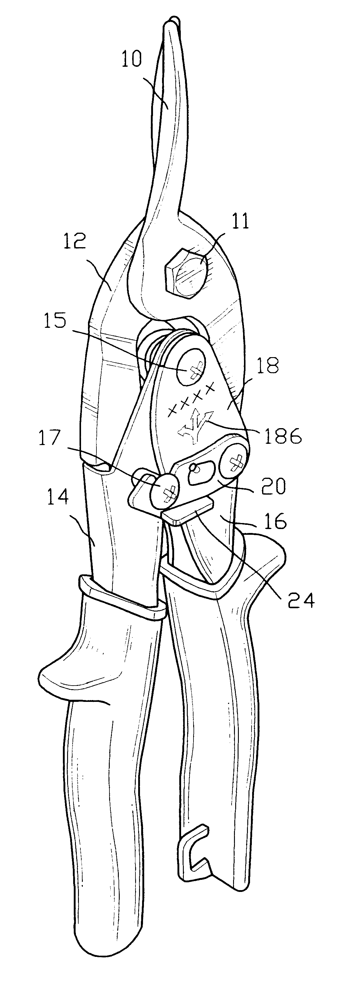
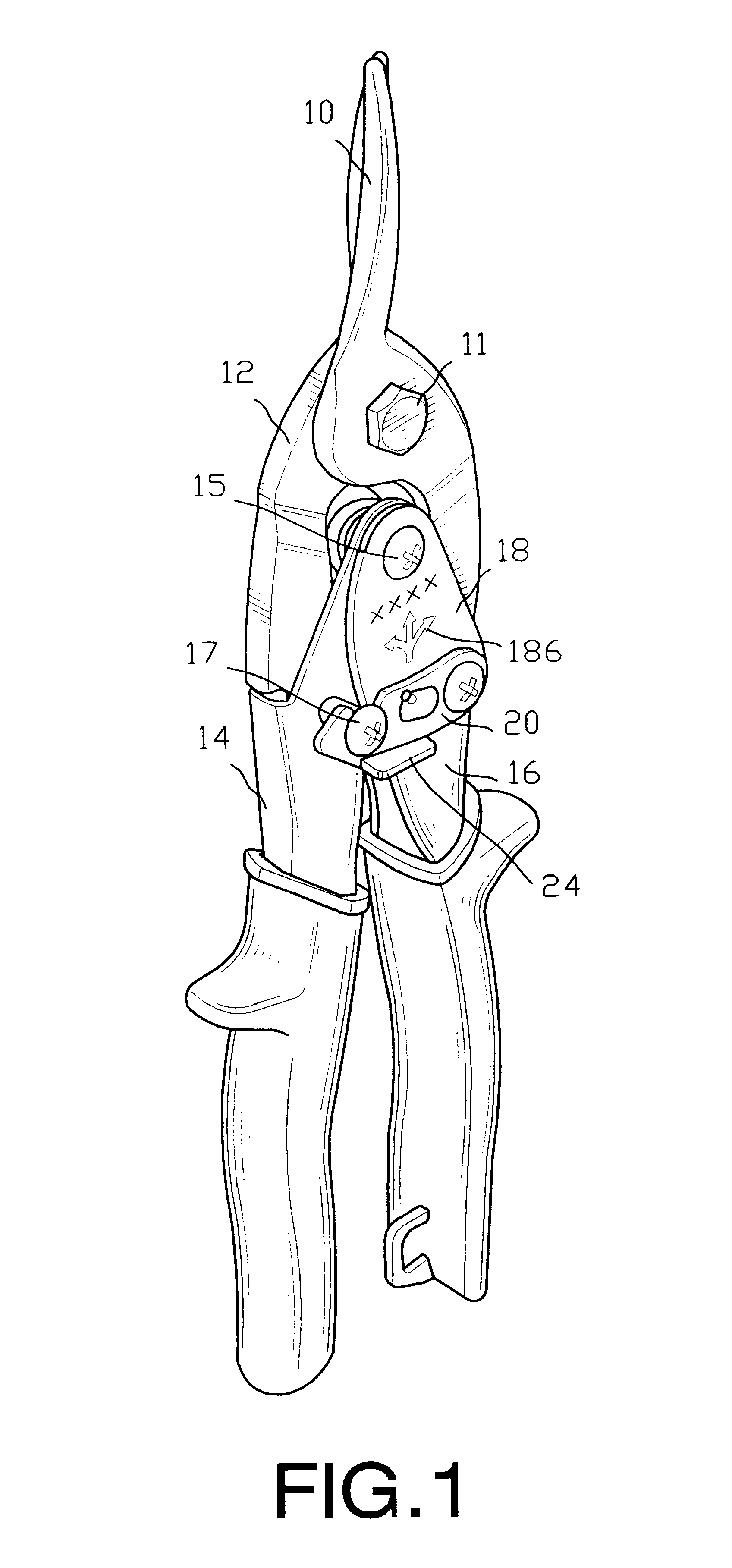
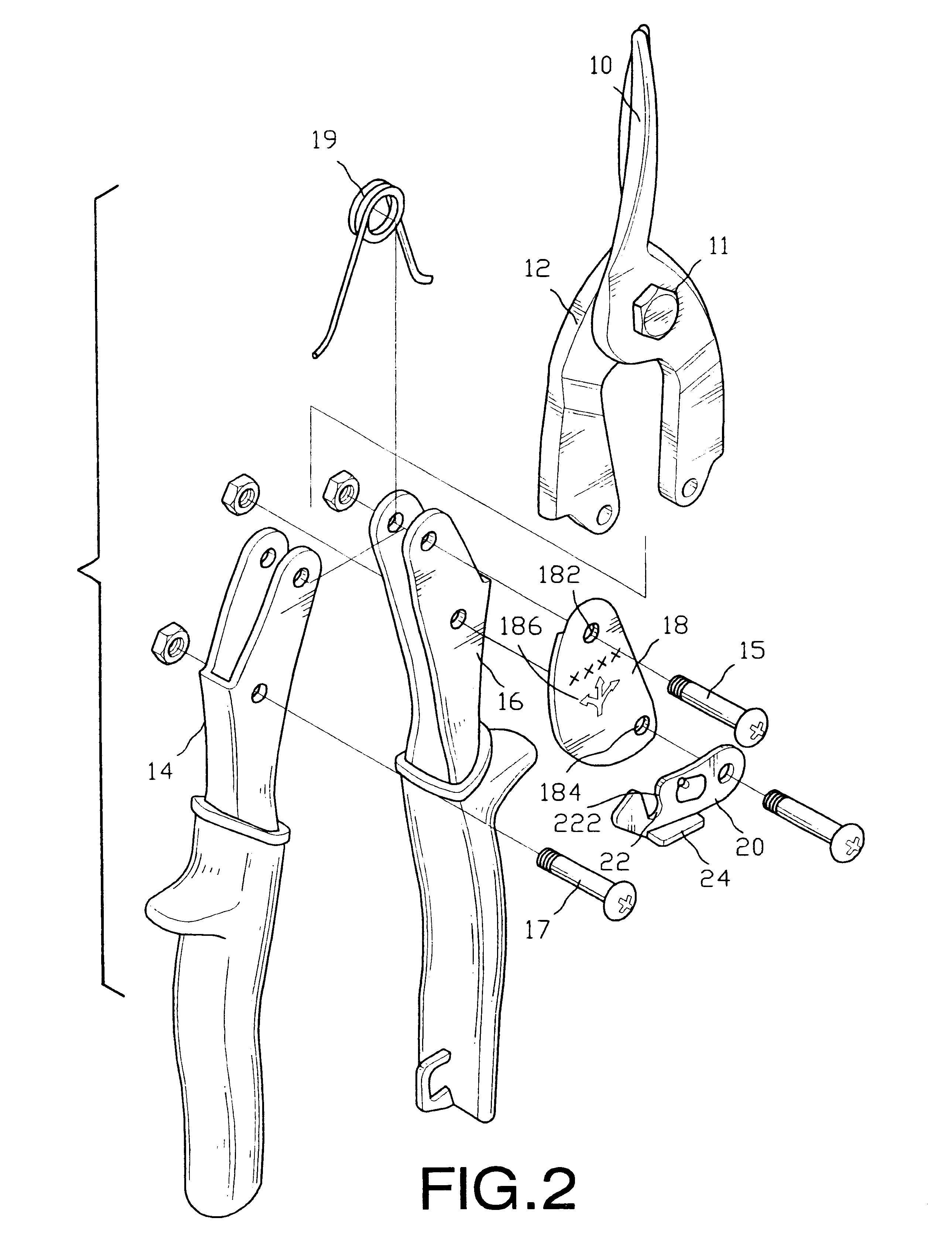
With reference to FIGS. 1 and 2, a pair of metal shears in accordance with the present invention comprises two blades (10, 12), two handles (14, 16) and a tag (18). The blades (10, 12) are pivotally attached to each other with a first pivot pin (11). The handles (14, 16) are pivotally attached to each other with a second pivot pin (15). Each blade (10, 12) is pivotally attached to a respective one of the handles (14, 16) with a third pivot pin (17). A spring (19) is mounted between the two handles (14, 16) to provide a biasing force to push the handles (14, 16) away from each other.

The tag (18) is securely attached to one of the handles (14, 16). In practice, the tag (18) is made of a plastic material. Two bores (182, 184) are defined in the tag (18) respectively for the second pivot pin (15) and one of the third pivot pins (17) to extend through the bores (182, 184). Some information or instructions are printed on the tag (18) to show the features of the pair of metal shears. For e...


PUM

PropertyMeasurementUnit
angleaaaaaaaaaa
angleaaaaaaaaaa
biasing forceaaaaaaaaaa

Abstract

A pair of metal shears has two blades, two handles, a tag and a locking lever. The blades are pivotally connected to each other with a first pivot pin. The handles are pivotally connected to each other with a second pivot pin. Each handle is pivotally connected to one of the blade with a third pivot pin. The tag is attached to one of the handles to show information of the pair of metal shears. The locking lever is pivotally attached to one of the handles to engage with the other handle. With such an attached tag, the information or instructions about the metal shears can be clearly shown on the tag.

Description

1. Field of the InventionThe present invention relates to a pair of metal shears, and more particularly to metal shears with an attached tag to clearly show the information about the shears.2. Description of Related ArtWith reference to FIG. 10, a pair of conventional metal shears in accordance with the prior art comprises two blades (30, 32) and two handles (34, 36). The blades (30, 32) are pivotally connected to each other with a first pivot pin (31). The handles (34, 36) are pivotally connected to each other with a second pivot pin (35). Each handle (34, 36) is pivotally attached to a respective one of the blades (30, 32) with a third pivot pin (37). A spring (not shown) is mounted between the handles (34, 36) to provide a biasing force to push the handles (34, 36) apart. To avoid a user, especially a child, being cut by the blades (30, 32) when holding or playing with the metal shears, a locking lever (38) is pivotally attached to one handle (36) and engages with the third pivot...

Claims


Application Information

Patent Timeline
Patent Type & Authority Patents(United States)
IPC IPC(8): B23D29/00B23D29/02
CPCB23D29/02
Inventor HUANG, HSIN-TE
Owner HUANG HSIN TE
Why Eureka
Try Eureka