Fastener for lace

a technology of fasteners and lace, which is applied in the field of fasteners, can solve the problems of loosening the lace, lace can be unintentionally pushed, and the problem of even worse,

Inactive Publication Date: 2003-12-16
LIN WEN CHI
View PDF9 Cites 27 Cited by
  • Summary
  • Abstract
  • Description
  • Claims
  • Application Information

AI Technical Summary

Problems solved by technology

However, when the sprig 4 is new, it exerts an inadequate force for fastening the sections of the lace, string, rope or the like 5, and this problem is even worse after it is used for some time.
Furthermore, the button 3 can be unintentionally pushed, thus loosening the lace, spring, rope or the like 5.

Method used


Image

  • Fastener for lace
  • Fastener for lace
  • Fastener for lace

Examples


Embodiment Construction

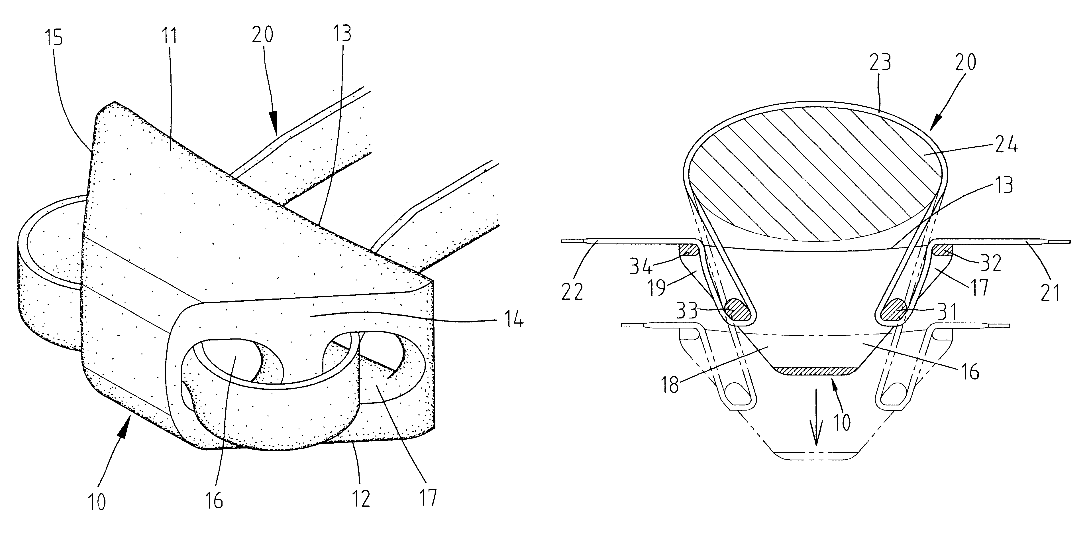
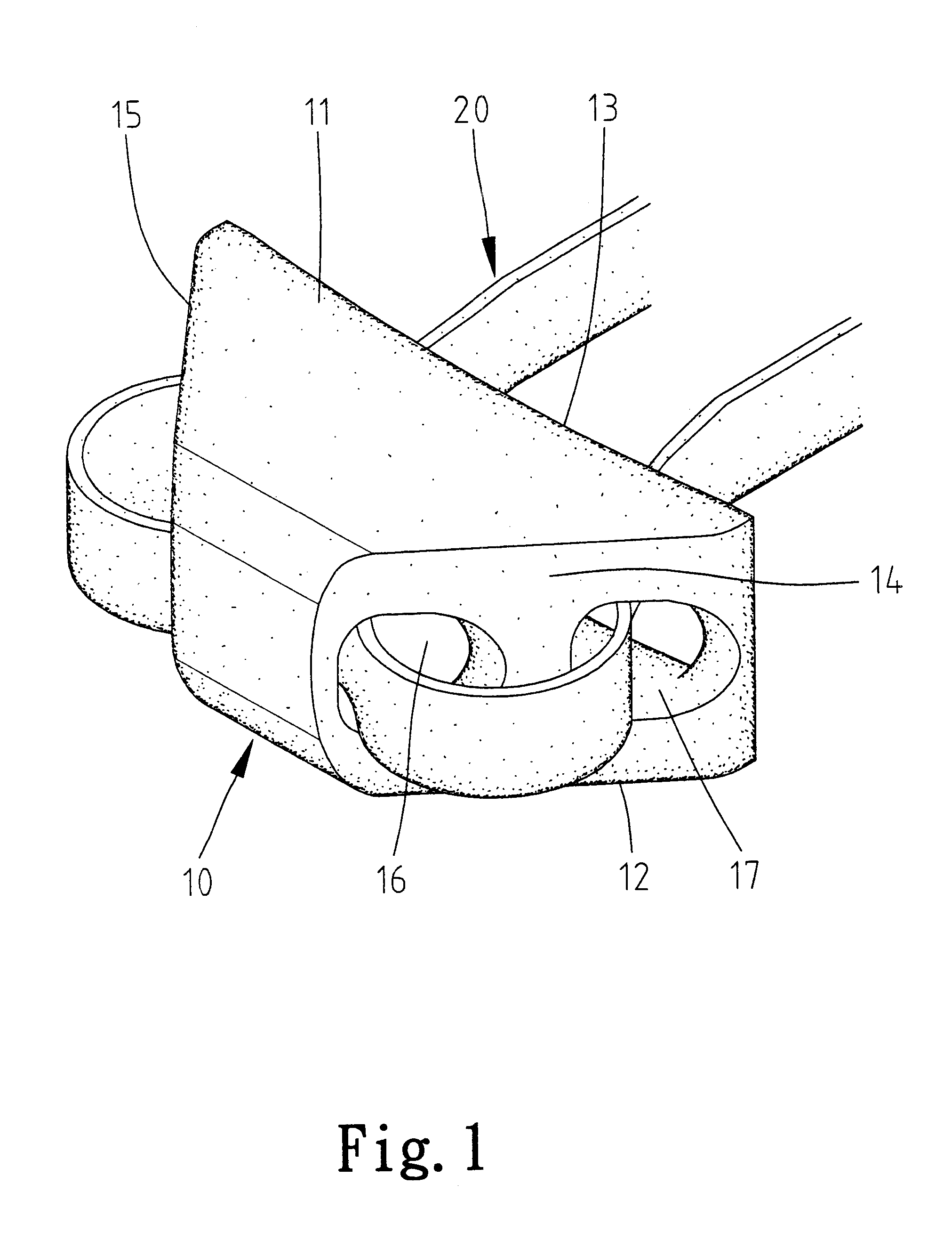
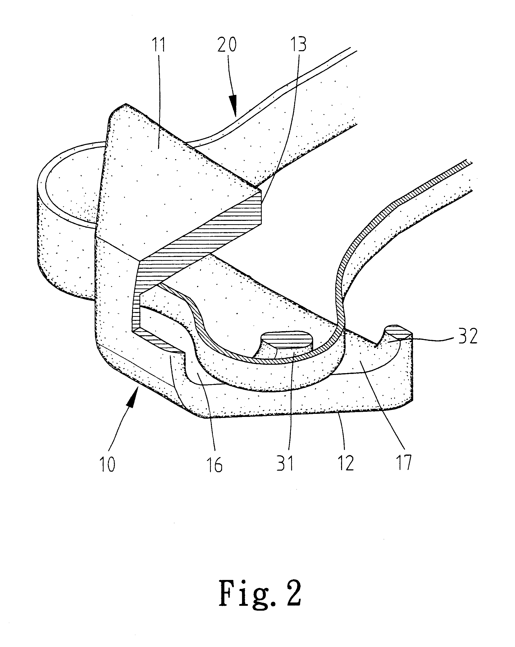
Referring to FIGS. 1-3, according to the preferred embodiment of the present invention, a fastener 10 is a hollow element through which a lace, string, rope or the like, hereinafter referred to as lace 20, can be inserted.

The fastener 10 includes an upper plate 11, a lower plate 12, a front portion (not numbered), a first lateral portion 14 and a second lateral portion 15. The upper plate 11 and the lower plate 12 are both shaped as an equilateral trapezoid (or "trapezium" as used in the UK) with a first lateral edge, a second lateral edge as long as the first lateral edge, a front edge and a rear edge longer than the font edge. The first lateral portion 14 extends between the first lateral ed of the upper plate 11 and the first lateral edge of the lower plate 12. The second lateral portion 15 extends between the second lateral edge of the upper plate 11 and tile second lateral edge of the lower plate 12. The first lateral portion 14 defines two holes 16 and 17, thus forming a first...


PUM


Abstract

A fastener for lace includes an upper plate, a lower plate and first, second, third and fourth rods extending between the upper and lower plates. The upper and lower plates both include a front edge, a rear edge, a first lateral edge and a second lateral edge. The first and second rods extend between the first lateral edge of the upper plate and the first lateral edge of the lower plate. The third and fourth rods extend between the second lateral edge of the upper plate and the second lateral edge of the lower plate. A first length of lace is wound about the first rod and directed past the second rod. A second length of lace is wound about the third rod and directed past the fourth rod.

Description

1. Field of InventionThe present invention relates to a fastener for a lace, string, rope or the like.2. Related Prior ArtReferring to FIG. 11, a conventional fastener for laces, strings and ropes is shown. This conventional fastener includes a housing 2, a spring 4 and a control element including a button 3 and a rod 6 extending from the button 3. The housing 2 defines two holes 7. The spring 4 is put in the housing 2. The button 3 is located outside the housing 2. The rod 6 defines a hole 8. The rod 6 is inserted in the housing 2 and is biased by means of the spring 4. In use, the rod 6 is pushed down via pressing the button 3 so that the axis of the holes 7 is aligned with the axis of the hole 8. Two sections of a lace, string, rope or the like 5 are inserted through the holes 7 and 8. Then, the push button 3 is released so that the sections of the lace, string, rope or the like 5 are fastened by means of the rod 6 and the housing 2. However, when the sprig 4 is new, it exerts an...

Claims


Application Information

Patent Timeline
Patent Type & Authority Patents(United States)
IPC IPC(8): A43C7/00
CPCA43C7/00Y10T24/3705Y10T24/3734Y10T24/3916Y10T24/3703Y10T24/3724Y10T24/3742
Inventor LIN, WEN-CHI
Owner LIN WEN CHI
Why Eureka
Try Eureka