Clamp having bendable shaft

a clamping device and shaft technology, applied in the field of medical devices, can solve the problems of affecting the surgeon's access to the surgical site, clamping poses significant access problems to the surgeon,

Inactive Publication Date: 2004-01-13
VITALTEC INT
View PDF29 Cites 330 Cited by
  • Summary
  • Abstract
  • Description
  • Claims
  • Application Information

AI Technical Summary

Benefits of technology

It is another object of the present invention to provide a clamp that can effectively clamp a blood vessel at a surgical site.
Alternatively, the surgeon can push the dial 406 in the distal direction indicated by the arrow A in FIG. 31, thereby pivoting the ratchet 400 about the pivot point 175a so that the worm gear 402 is pivoted in the direction of the arrow C in FIG. 31, which releases the engagement between the worm gear 402 and the tooth 125a. Thus, the dial 406 also operates as a lever to pivot the ratchet 400.

Problems solved by technology

As a result, such conventional clamps are bulky and can interfere with the surgeon's access to the surgical site.
As a result, the conventional clamps pose significant access problems to the surgeon when used during minimally invasive surgical procedures.

Method used


Image

  • Clamp having bendable shaft
  • Clamp having bendable shaft
  • Clamp having bendable shaft

Examples


Embodiment Construction

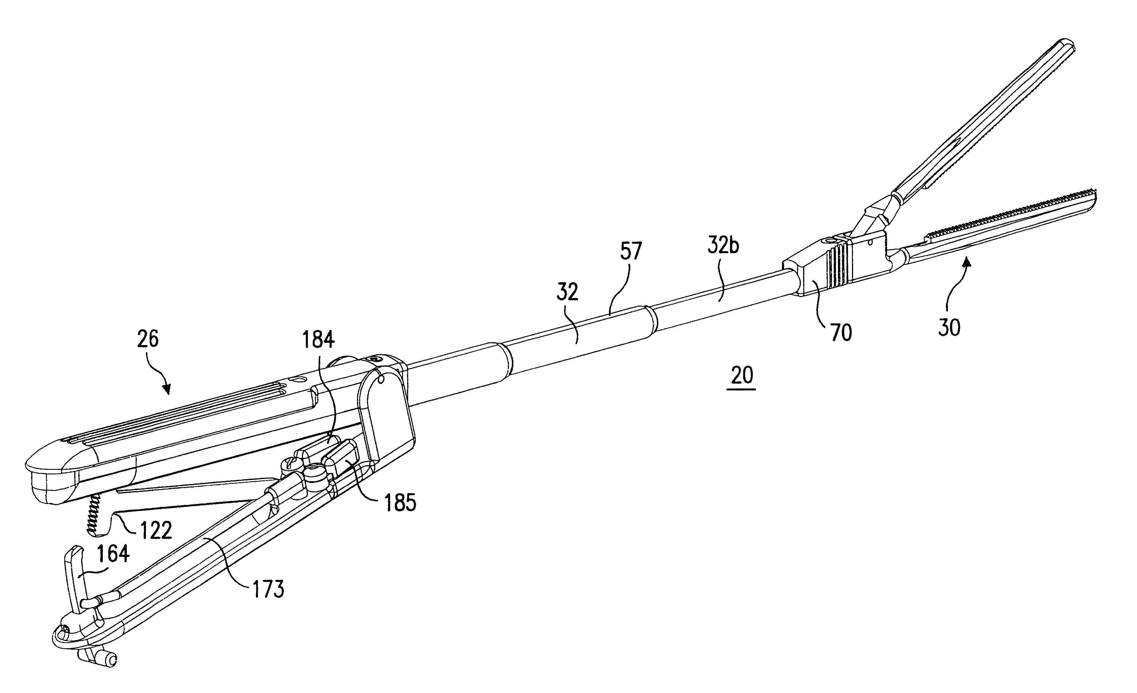
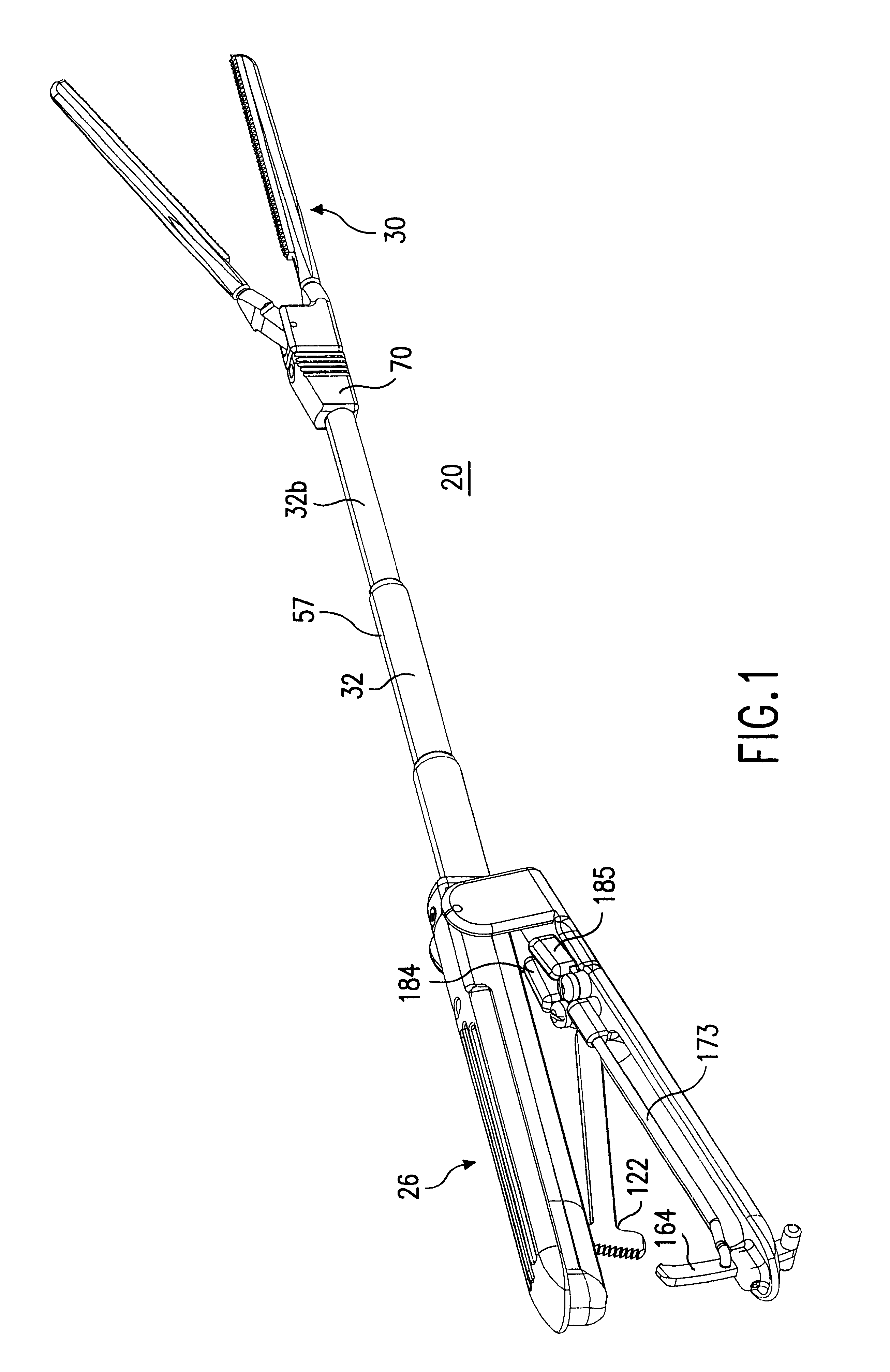
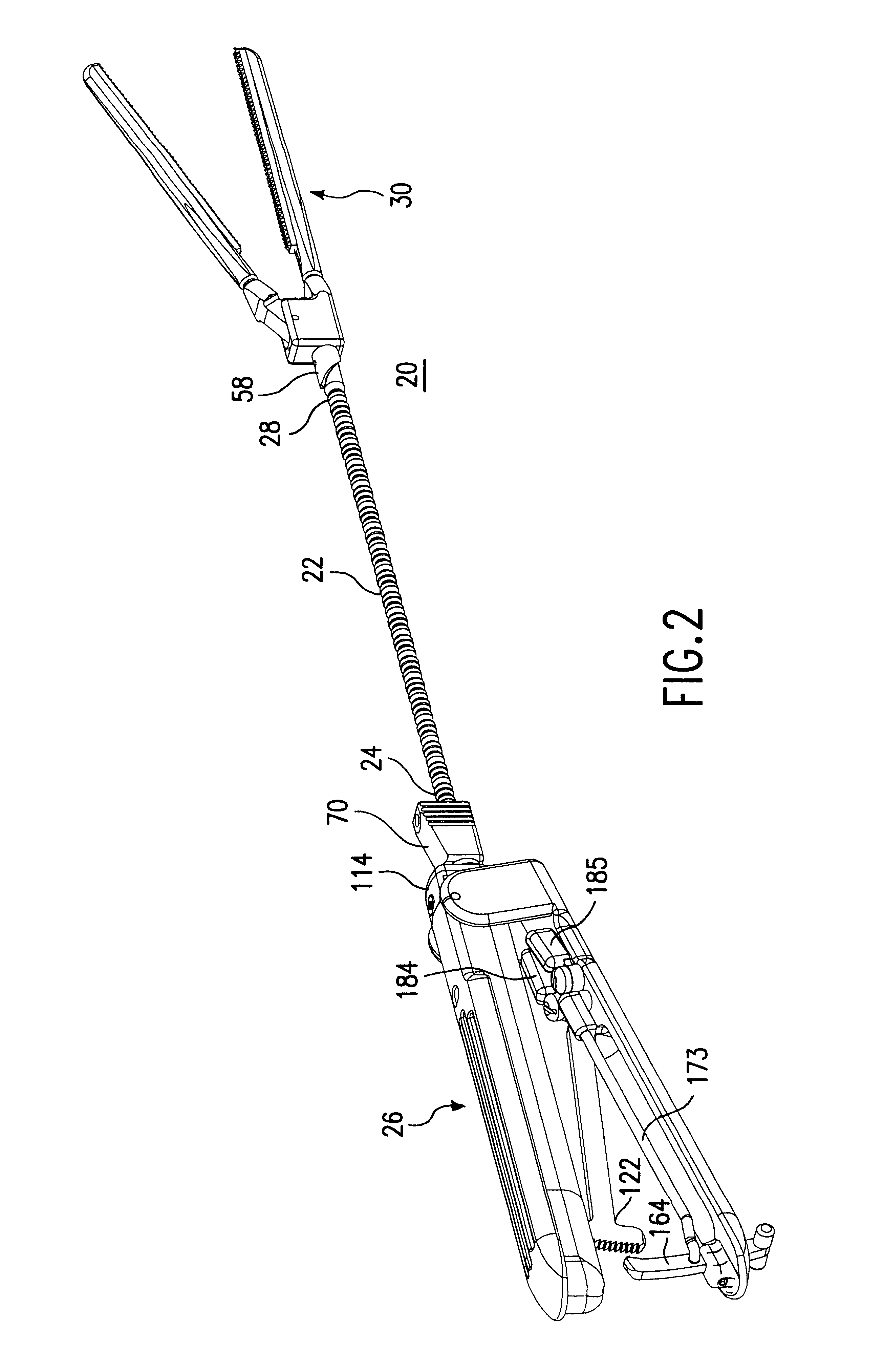
The clamps 20 and 20h of the present invention are especially well-suited for use in minimally-invasive procedures where the jaws 260, 262 can be introduced through a port, trocar or small incision (hereinafter collectively referred to as "Port"). In this Example, the same numerals are used to designate the same corresponding elements in both the clamps 20 and 20h. Such minimally-invasive procedures can include applications such as endoscopic or laproscopic applications. For example, during a minimally-invasive procedure, a surgeon may need to use an endoscope to view the surgical activity at the site of the procedure. In such minimally-invasive procedures, the Port is of a small size such that the surgeon's hands cannot readily access the surgical site through the Port. As a result, the surgeon can only manipulate the jaws 260, 262 via the handle assembly 26 or the knob 70h.

When used in a minimally-invasive procedure, the surgeon grips the handle pieces 116, 216 to close the jaws 2...


PUM


Abstract

A clamp has a handle assembly, a gripping assembly having a pair of jaws that can be opened and closed to grip an element, and a shaft assembly. The shaft assembly has a flexible shaft having a proximal end that is operatively coupled to the handle assembly and a distal end that is operatively coupled to the gripping assembly. The shaft assembly also has a rigid element that can be placed in a first position where the rigid element supports the shaft in a manner where the shaft cannot be bent, and in a second position where the shaft can be bent.

Description

1. Field of the InventionThe present invention relates to medical devices, and in particular, to a clamping device that has a bendable shaft.2. Description of the Prior ArtClamping devices are typically used to occlude blood vessels during a surgical procedure. Conventional clamping devices are also known as clamps, and have a shaft that connects a pair of jaws with a handle at opposite ends thereof. The pair of jaws open and close about a pivot point in a motion that resembles that of a scissors. These conventional clamps are typically made from stainless steel and the shaft is therefore completely rigid. As a result, such conventional clamps are bulky and can interfere with the surgeon's access to the surgical site. To address this problem, elastic bands were sometimes used to hold the handles of the clamp away from the location of the surgical site.With the increasing popularity of minimally invasive surgical procedures, access to the surgical site is reduced, thereby creating a ...

Claims


Application Information

Patent Timeline
Patent Type & Authority Patents(United States)
IPC IPC(8): A61B17/122A61B17/12A61B17/28A61B19/00A61B17/00
CPCA61B17/122A61B2017/00314A61B2017/2837A61B2017/2901A61B2017/2905A61B2017/2946A61B19/26A61B2017/00292A61B90/50
Inventor DANITZ, DAVID J.HEGEMAN, DAVID E.GOLD, ADAM C.
Owner VITALTEC INT
Why Eureka
Try Eureka