Clamp having bendable shaft

Inactive Publication Date: 2002-11-07
VITALTEC INT
View PDF0 Cites 15 Cited by
  • Summary
  • Abstract
  • Description
  • Claims
  • Application Information

AI Technical Summary

Benefits of technology

0008] It is an object of the present invention to provide a clamp that do

Problems solved by technology

As a result, such conventional clamps are bulky and can interfere with the surgeon's access to the surgical site.
As a result, t

Method used


Image

  • Clamp having bendable shaft
  • Clamp having bendable shaft
  • Clamp having bendable shaft

Examples


Embodiment Construction

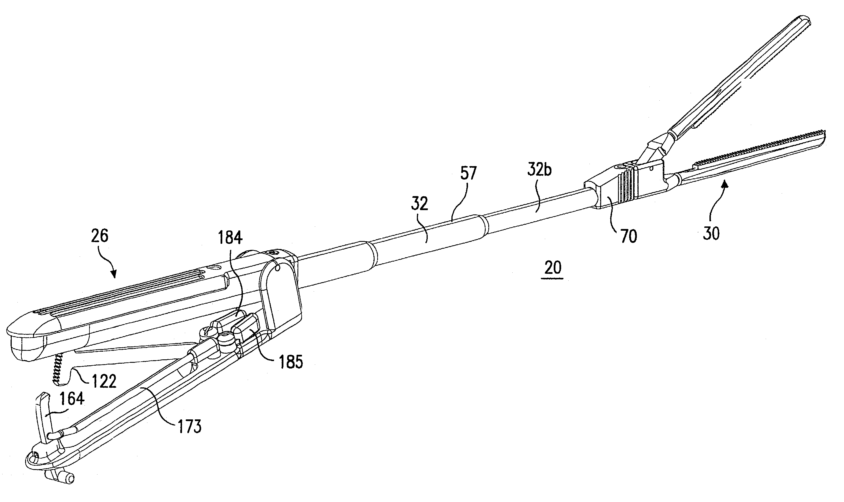
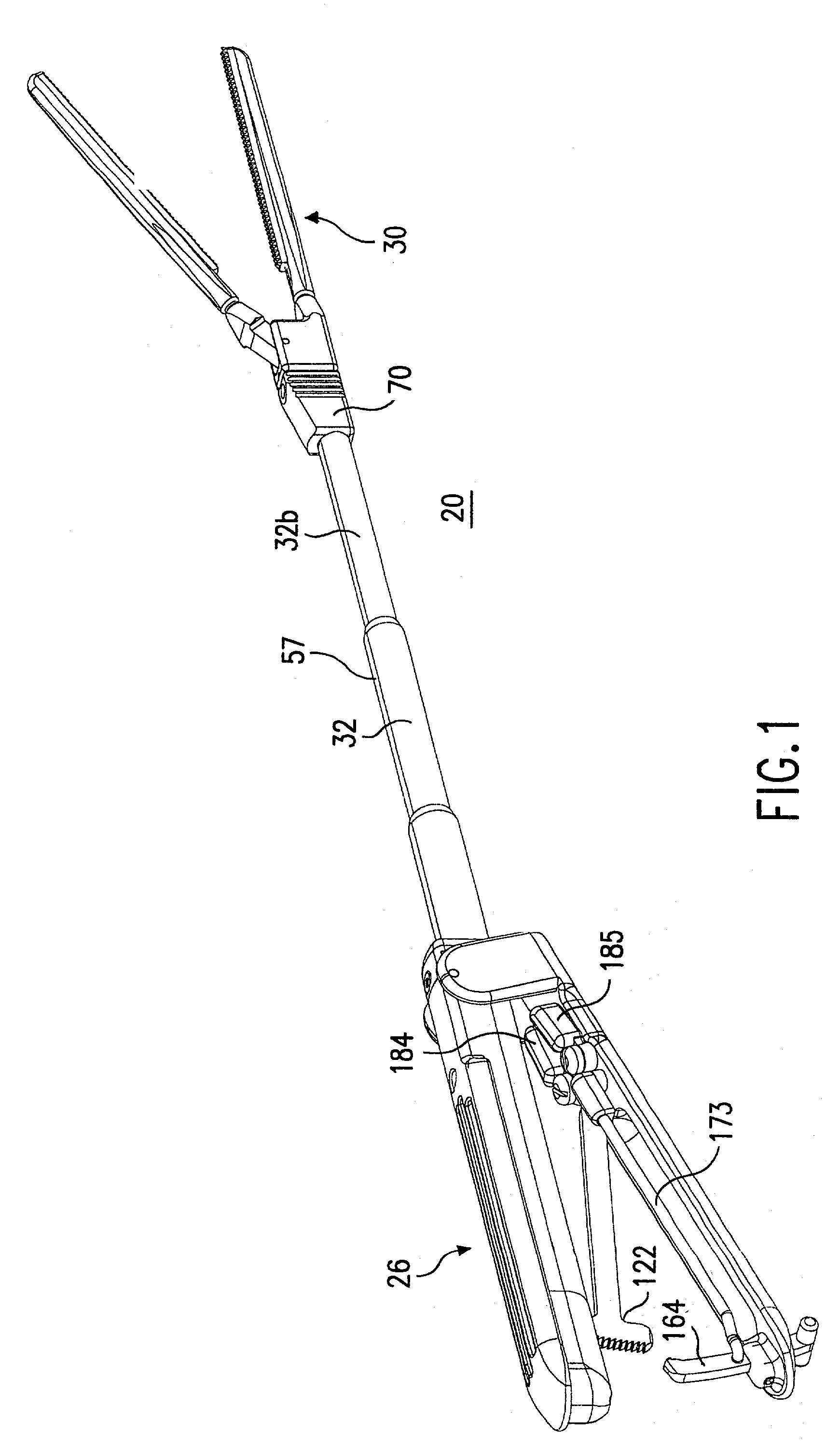
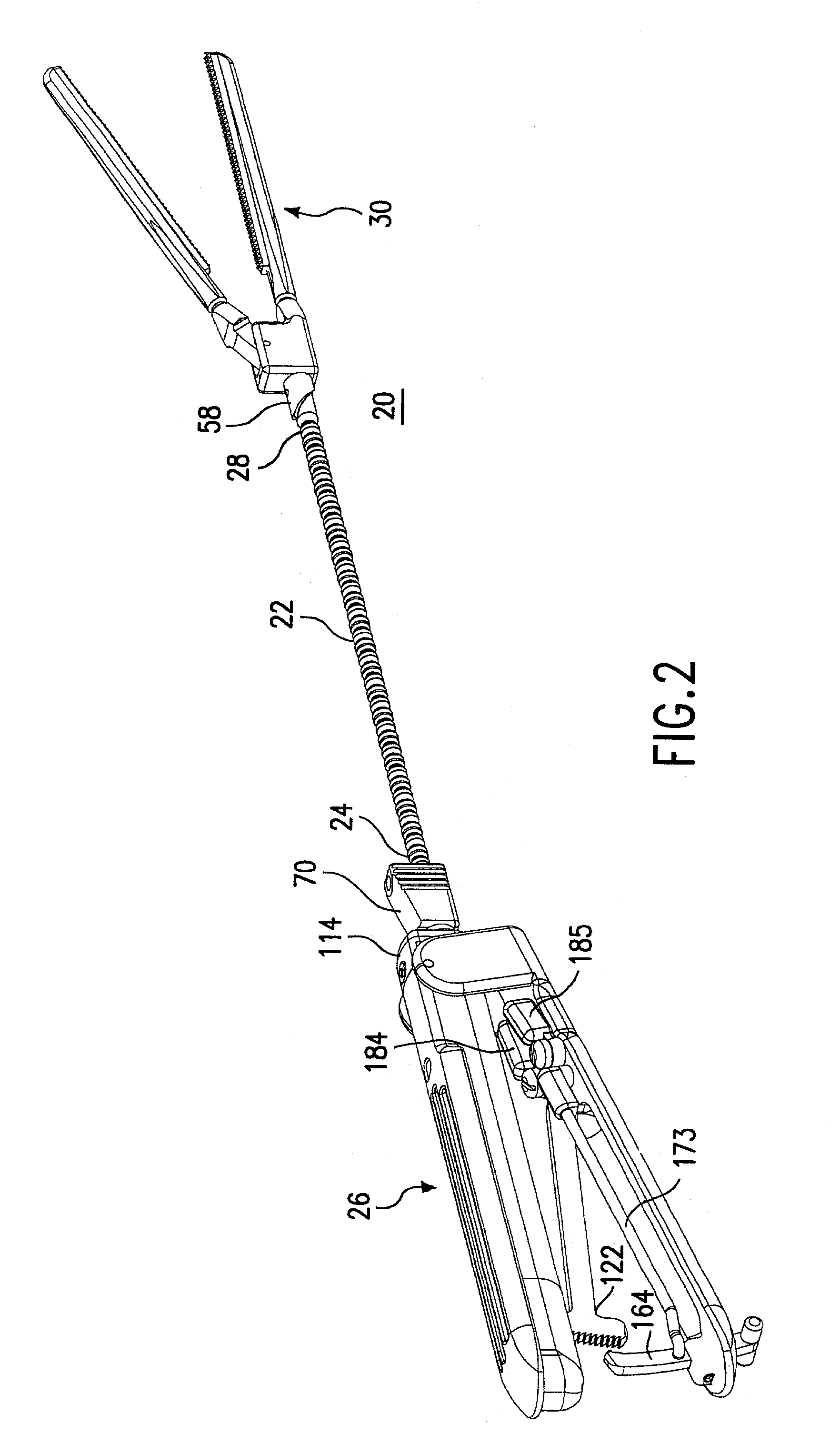
[0107] The clamp 20 of the present invention is especially well-suited for use in minimally-invasive procedures where the jaws 260, 262 can be introduced through a port, trocar or small incision (hereinafter collectively referred to as "Port"). Such minimally-invasive procedures can include applications such as endoscopic or laproscopic applications. For example, during a minimally-invasive procedure, a surgeon may need to use an endoscope to view the surgical activity at the site of the procedure. In such minimally-invasive procedures, the Port is of a small size such that the surgeon's hands cannot readily access the surgical site through the Port. As a result, the surgeon can only manipulate the jaws 260, 262 via the handle assembly 26.

[0108] When used in a minimally-invasive procedure, the surgeon grips the handle pieces 116, 216 to close the jaws 260, 262, and then introduces the closed jaws 260, 262 and a portion of the shaft 22 through the Port into the interior of a patient....


PUM


Abstract

A clamp has a handle assembly, a gripping assembly having a pair of jaws that can be opened and closed to grip an element, and a shaft assembly. The shaft assembly has a flexible shaft having a proximal end that is operatively coupled to the handle assembly and a distal end that is operatively coupled to the gripping assembly. The shaft assembly also has a rigid element that can be placed in a first position where the rigid element supports the shaft in a manner where the shaft cannot be bent, and in a second position where the shaft can be bent.

Description

RELATED CASES[0001] This is a continuation-in-part of application Ser. No. 09 / 847,135, filed May 2, 2001, whose disclosure is incorporated by this reference as though set forth fully herein.[0002] 1. Field of the Invention[0003] The present invention relates to medical devices, and in particular, to a clamping device that has a bendable shaft.[0004] 2. Description of the Prior Art[0005] Clamping devices are typically used to occlude blood vessels during a surgical procedure. Conventional clamping devices are also known as clamps, and have a shaft that connects a pair of jaws with a handle at opposite ends thereof. The pair of jaws open and close about a pivot point in a motion that resembles that of a scissors. These conventional clamps are typically made from stainless steel and the shaft is therefore completely rigid. As a result, such conventional clamps are bulky and can interfere with the surgeon's access to the surgical site. To address this problem, elastic bands were sometim...

Claims


Application Information

Patent Timeline
IPC IPC(8): A61B17/12A61B17/00A61B17/122A61B17/28A61B19/00
CPCA61B2017/2946A61B19/26A61B17/122Y10T74/20456A61B2017/2905A61B2019/266A61B2017/00292A61B2017/2837A61B2017/2901A61B90/50A61B2090/508
Inventor DANITZ, DAVID J.HEGEMAN, DAVID E.GOLD, ADAM C.
Owner VITALTEC INT
Why Eureka
Try Eureka