Bridged capacitor sensor measurement circuit

a capacitor sensor and measurement circuit technology, applied in capacitance measurement, resistance/reactance/impedence, instruments, etc., can solve problems such as system instability, system non-convergent integration, and system instability

Inactive Publication Date: 2004-04-13
ROSEMOUNT INC
View PDF7 Cites 48 Cited by
  • Summary
  • Abstract
  • Description
  • Claims
  • Application Information

AI Technical Summary

Benefits of technology

The present invention employs a reference capacitor that is larger than the expected maximum difference .vertline.C.sub.1 -C.sub.2.vertline..sub.max between the two capacitors of the differential pair. Consequently, the sign of the difference C.sub.1 -C.sub.2 will not cause non-convergence of the integration process. Moreover, the value of the capacitance of C.sub.REF can be established such that the output signals of the converter will not saturate.

Problems solved by technology

Unfortunately, such a converter system may become unstable.
When the increment proportional to (C.sub.1 -C.sub.2) has the same polarity as the increment proportional to the reference capacitor C.sub.REF, the system becomes a non-convergent integration system and is unstable.

Method used


Image

  • Bridged capacitor sensor measurement circuit
  • Bridged capacitor sensor measurement circuit
  • Bridged capacitor sensor measurement circuit

Examples


Embodiment Construction

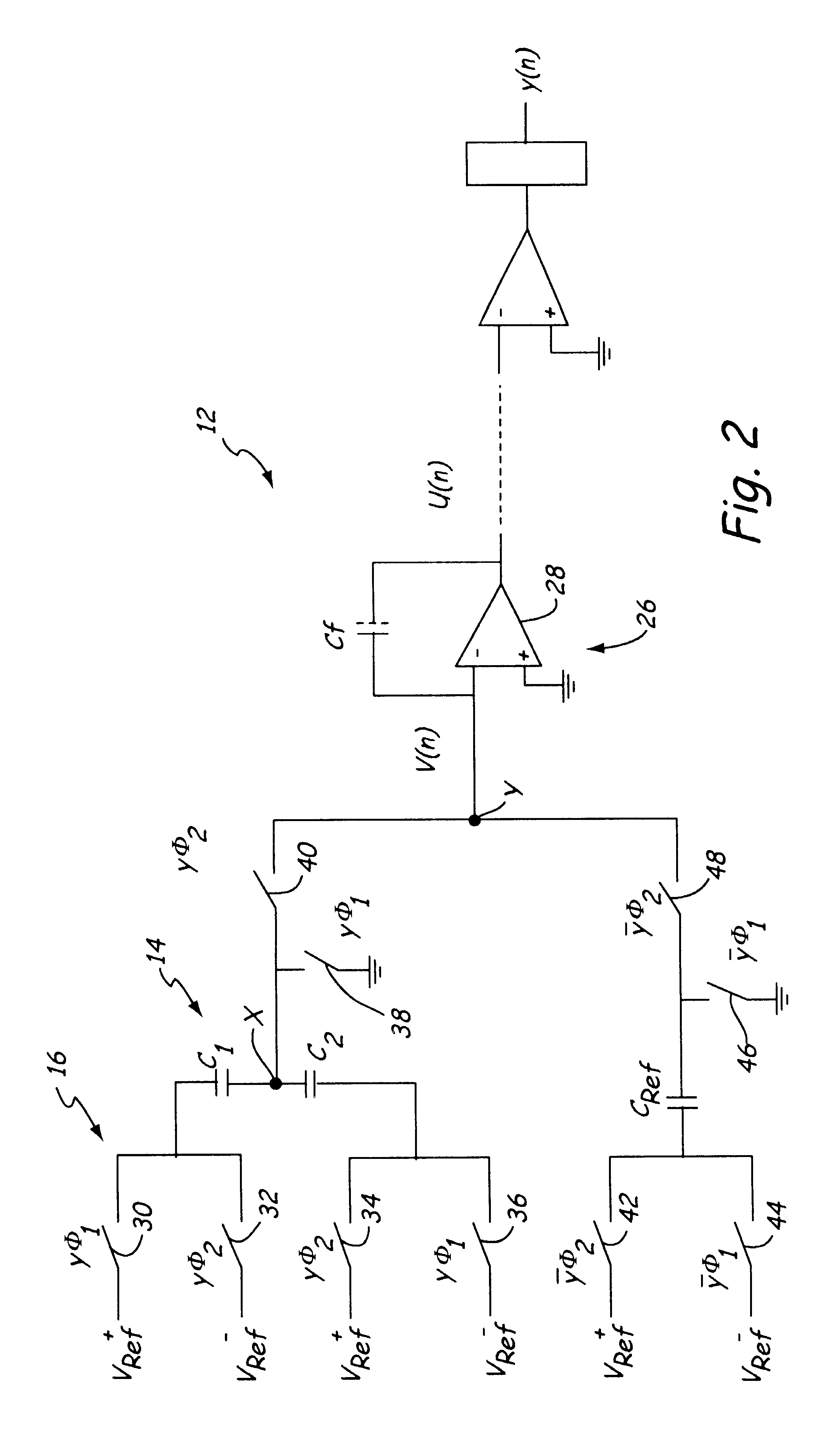
The principal problem addressed by the present invention is that prior differential converters were not always convergent, leading to instability. The present invention employs a reference capacitance that is larger than the expected maximum difference between the differential capacitors so that the converter is convergent and the integrator will not saturate.

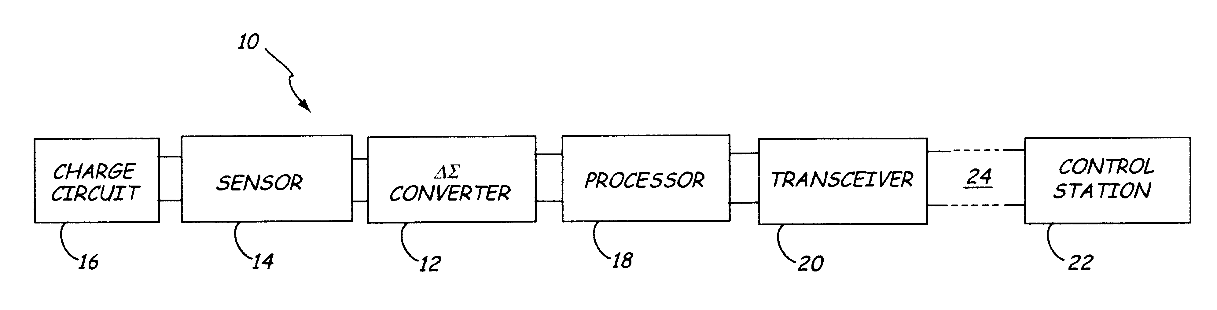
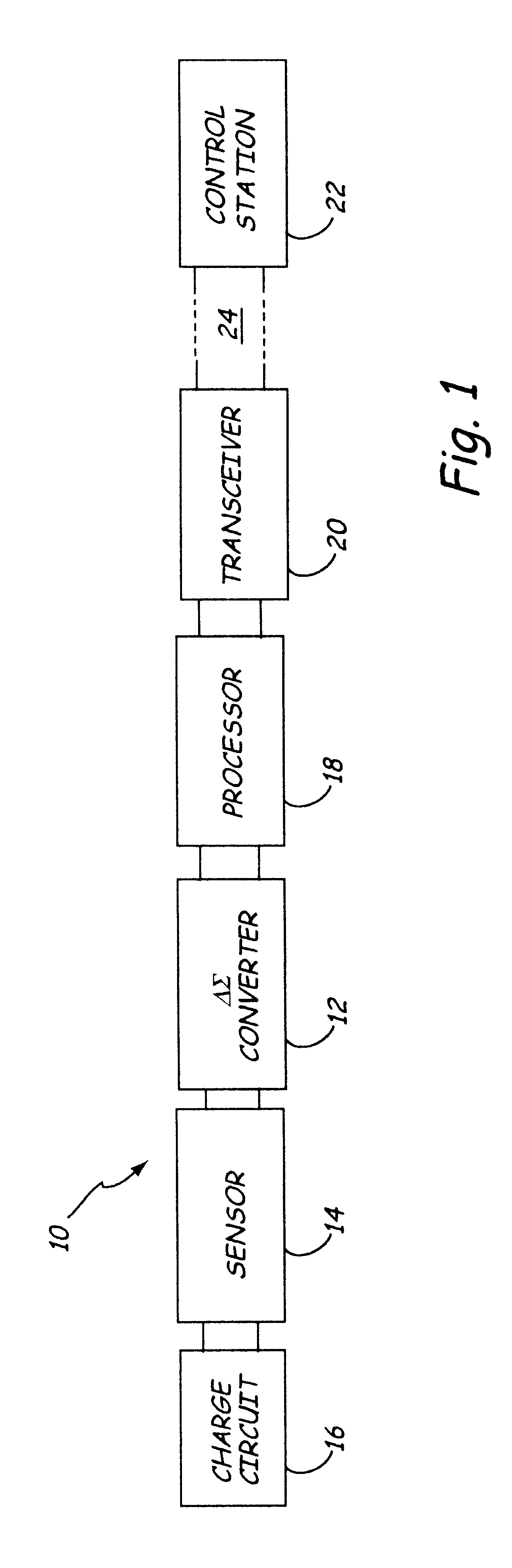
FIG. 1 is a block diagram of an industrial process control transmitter 10 having a capacitance-to-digital converter 12, such as a delta sigma converter, arranged to receive signals representative of a pressure from sensor 14. Sensor 14 is a differential sensor that includes at least a pair of pressure sensitive capacitors that are charged by charge circuit 16. One example of sensor 14 is a pair of absolute pressure sensors as described in the aforementioned Frick et al. patent. Charges on the capacitors are representative of pressure and are transferred to converter 12 which converts the charges to digital signals. The digital ...


PUM

PropertyMeasurementUnit
voltageaaaaaaaaaa
voltageaaaaaaaaaa
voltageaaaaaaaaaa

Abstract

A pair of sensing capacitors, each having a capacitance C.sub.1 and C.sub.2 respectively, based on a process variable, are coupled to a bridge node which is coupled to a summing node. A reference capacitor, coupled to the summing node, has a capacitance C.sub.REF greater than an expected maximum difference between the capacitances of the pair of sensing capacitors. Switches selectively couple the sensing capacitors and the reference capacitor to at least first and second voltages to derive charges representative of C.sub.1 -C.sub.2 and C.sub.REF. In one embodiment the sensing capacitors are operated to charge and discharge during respective first and second phases of first cycles and the reference capacitor is operated to charge and discharge during respective first and second phases of second cycles. In another embodiment, the reference capacitor is operated to charge and discharge during alternate phases of the first and second cycles and the sensing capacitors are operated to charge and discharge during respective first and second phases of all cycles.

Description

FIELD OF THE INVENTIONThis invention relates to industrial process control transmitters, and particularly to apparatus that increases the stability of a differential sensor or sensor pair for such a transmitter.BACKGROUND OF THE INVENTIONIndustrial process control transmitters are used to measure process variables of fluids in an industrial process. Typically, these transmitters are placed in field locations and provide standardized transmission signals representing process variable of the monitored fluid, such as pressure. The fluids include slurries, liquids, vapors and gasses, in industrial process plants, such as chemical, pulp, petroleum, gas, pharmaceutical, food and other fluid processing plants. The monitored process variables can be pressure, temperature, flow, level, pH, conductivity, turbidity, density, concentration, chemical composition or other properties of fluids.An industrial process control transmitter typically includes a sensor that senses the process variable, a...

Claims


Application Information

Patent Timeline
Patent Type & Authority Patents(United States)
IPC IPC(8): G01R27/26G01D1/00G01L9/00
CPCG01R27/2605
Inventor WANG, RONGTAI
Owner ROSEMOUNT INC
Why Eureka
Try Eureka