Method of preparing hydroformed metallic golf club shafts

a golf club shaft and hydroformed technology, applied in the field of hydroformed metallic golf club shafts, can solve the problems of limited design and functionality of prior art golf club shafts and the process of making the sam

Inactive Publication Date: 2005-01-25
TRUE TEMPER SPORTS
View PDF33 Cites 19 Cited by
  • Summary
  • Abstract
  • Description
  • Claims
  • Application Information

AI Technical Summary

Benefits of technology

The shafts of the present invention are generally produced by the following process. First, a tube is formed by any of a number of procedures. In one method, a planar piece of metal is formed and welded into a tube. Alternatively, a seamless tube can be formed by an extrusion process. The tube is subsequently annealed at least once. Preformed or manufactured tubing could be otherwise be utilized. The tube is drawn over a number of mandrels producing a shaft blank. The shaft blank can have any number or multitude of thicknesses, i.e. generally from 1 to about 10 and preferably from 1 to about 6, with a constant outer diameter at this point in the process. The shaft is then end formed by compressing the tube axially through a series of cylindrical dies, the inside diameters of the dies being less than the shaft outer diameter, to produce a step

Problems solved by technology

The prior art golf club shafts and processes for making the same have

Method used


Image

  • Method of preparing hydroformed metallic golf club shafts
  • Method of preparing hydroformed metallic golf club shafts
  • Method of preparing hydroformed metallic golf club shafts

Examples


Embodiment Construction

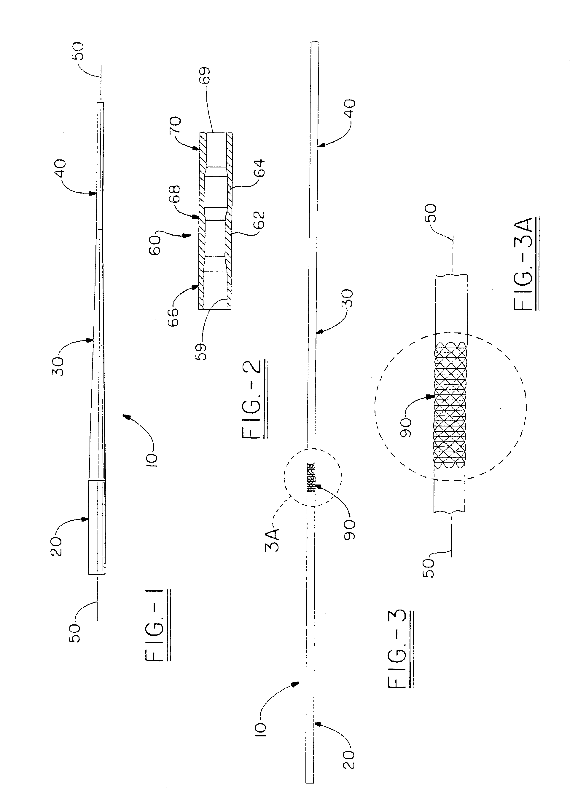
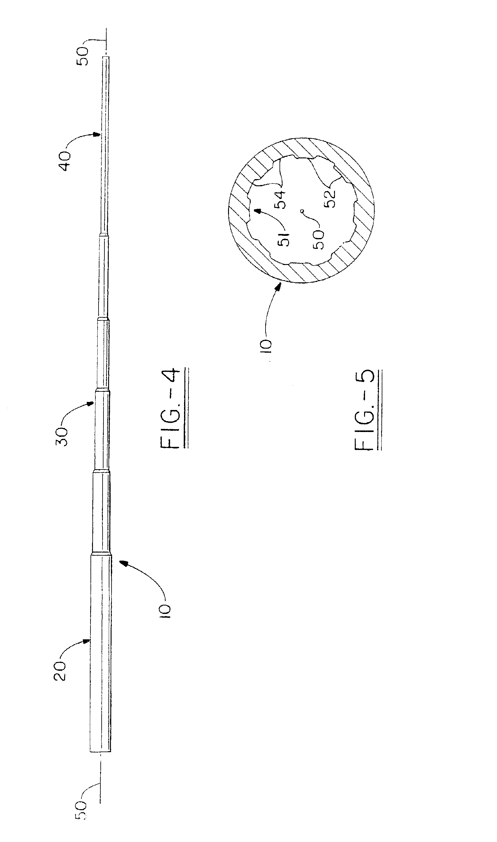
The present invention can be better understood by reference to the drawings, wherein FIG. 1 shows an example golf club shaft produced by the method of the present invention. The shaft 10 generally includes a grip or butt section 20, an intermediate section 30, which is preferably tapered, and a tip section 40. The shaft 10 has a substantially cylindrical shape, with the tip section having a smaller outer diameter than the grip section.

Preferably, the grip section and the tip section have constant or substantially constant outer diameters, i.e. having wall ends which appear parallel to each other when viewed from the side. It is also possible for the tip and grip sections to be tapered. Depending on the effect desired, the inner diameters of one or more of the shaft grip, intermediate, and tip sections can be varied along the length of the respective sections. The grip, intermediate, and tip sections 20, 30, 40 typically have a common central longitudinal axis 50, as shown in FIG. 1,...


PUM

PropertyMeasurementUnit
Fractionaaaaaaaaaa
Fractionaaaaaaaaaa
Fractionaaaaaaaaaa

Abstract

Method for preparing a golf club shaft, set of shafts, or golf clubs having shafts which have been produced by a process that includes a hydroforming step. By utilizing a hydroforming prosses step, a metal or metal matrix composite golf club shaft can be formed into a variety of configurations or shapes heretofore not possible and can include hydroformed ornamental design features.

Description

FIELD OF THE INVENTIONThe present invention relates to golf club shafts, in particular metal or metal matrix composite golf club shafts, which have been produced by a process that includes a hydroforming step. By utilizing a hydroforming step, a golf club shaft can be constructed having a variety of forms or shapes heretofore not possible. Advantageously, the hydroformed shafts can be configured to enhance club feel or performance, or even to include hydroformed ornamental design elements which can be located in any or all of a tip, grip, or intermediate sections of the shaft.BACKGROUND OF THE INVENTIONThe prior art golf clubs and shafts thereof have a degree of flexibility that is greatly dependent on the shaft material. Each individual golfer, especially a skilled player, has a preference for certain characteristics, such as feel, in a golf club or set of clubs. Generally feel is measured by the flexibility of the golf club shaft. One golfer may prefer a stiff feel, while others m...

Claims


Application Information

Patent Timeline
IPC IPC(8): A63B53/00A63B53/12B21K17/00B21D26/02B21D26/00
CPCA63B53/12B21D35/006B21K17/00B21D26/033A63B59/0014A63B2053/005Y10T29/49805A63B60/10A63B60/06A63B60/08A63B53/005A63B60/00A63B60/002
Inventor BLOUGH, ROBERT THOMAS
Owner TRUE TEMPER SPORTS
Why Eureka
Try Eureka