Down flow radial flow filter

a filter media and radial flow technology, applied in the direction of moving filter element filters, filtration separation, separation processes, etc., can solve the problem of increasing the pressure of backwash liquid, and achieve the effect of enhancing the fluidizing of the filter media

Inactive Publication Date: 2005-02-08
MARTIN JOHN D
View PDF7 Cites 11 Cited by
  • Summary
  • Abstract
  • Description
  • Claims
  • Application Information

AI Technical Summary

Benefits of technology

Other embodiment of the invention include different arrangements, such as O-rings, perforated bladders and check valves for enhancing the fluidizing of the filter media.

Problems solved by technology

As such, the pressure of the backwash liquid increases because there is no easy or unrestricted flow path from the backwash chamber into the upper portion of the mesh-covered inner perforated cylinder.

Method used


Image

  • Down flow radial flow filter
  • Down flow radial flow filter
  • Down flow radial flow filter

Examples


Embodiment Construction

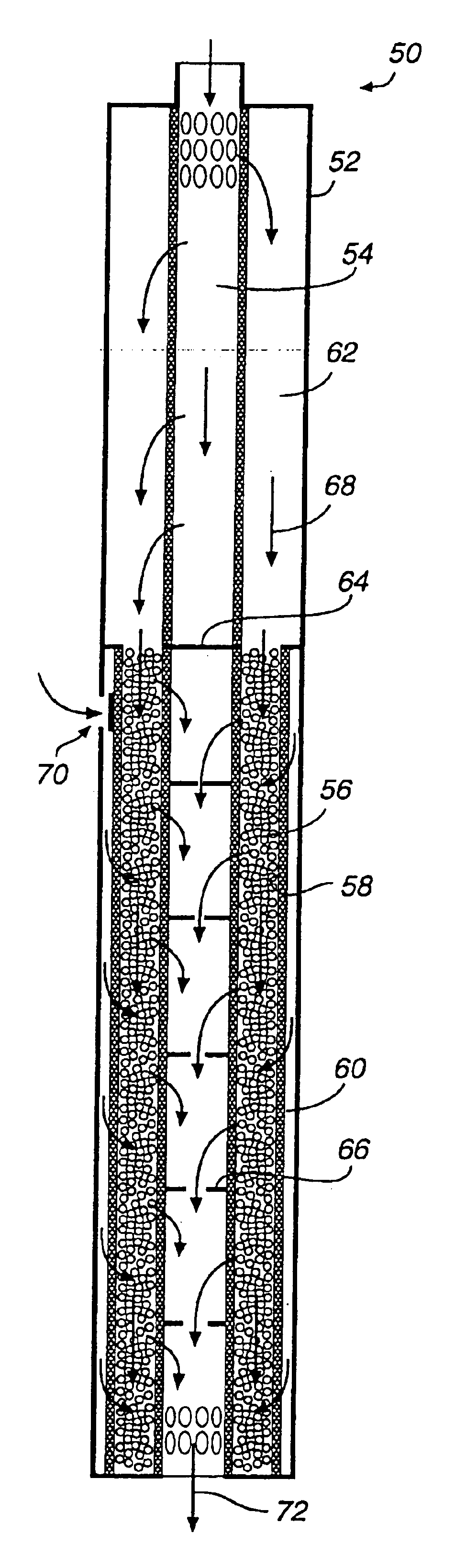
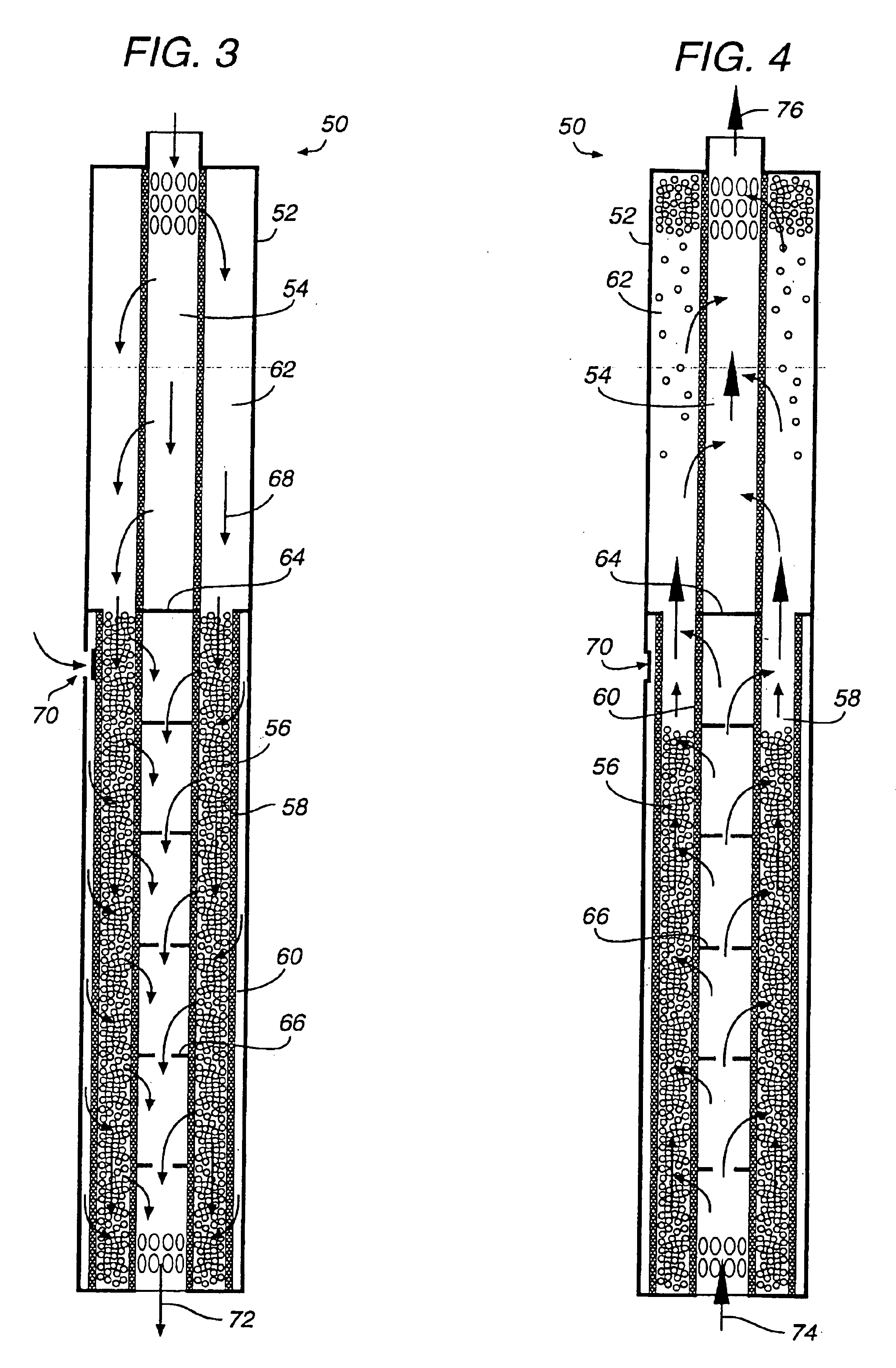
FIG. 3 illustrates in a generalized diagrammatic form, the radial-flow filter assembly 50 constructed in accordance with the invention. The radial-flow filter assembly 50 employs a new backwashing technique, thereby avoiding the downtime and expense of reconditioning the nonbonded porous media, as was periodically required by the prior art filters. While the preferred and other embodiments will be described in connection with a device using a granular filter media for filtering particulate matter from an influent, the principles and concepts of the invention can be utilized for coacting a media with an influent, a gas or liquid, where the media periodically requires backwashing to cleanse or regenerate the media.

The radial-flow filter assembly 50 is constructed with a rigid cylindrical housing 52 that extends the entire length of the filter assembly. An inner perforated cylinder 54 with a screen mesh extends the entire length of the filter housing 52. While not shown, the inner scre...


PUM

PropertyMeasurementUnit
diameteraaaaaaaaaa
pressureaaaaaaaaaa
radiiaaaaaaaaaa

Abstract

A method of coacting a fluid with a media, such as granular particles. The media is moved to an upper portion in an upright media container, and held there during a treatment cycle in which the fluid is coacted with the media. When the media requires regeneration, the media is allowed to fall to a lower portion of the media container where a regeneration fluid is passed through the media.

Description

TECHNICAL FIELD OF THE INVENTIONThis present invention relates in general to a device for coacting a porous media with an influent, or for removing impurities, solids or particulate matter from an influent, and more particularly to a radial-flow type of filter having a nonbonded filter media, and in which the flow of the fluids can be reversed in a backwash operation to remove the filtered matter and thus regenerate the filter for reuse.BACKGROUND OF THE INVENTIONWhile there exists many types of filters for removing particulate matter from an influent, such filters are generally classified as the type having a bonded or nonbonded media A bonded media filter includes a removable cartridge element constructed of a fibrous woven or nonwoven material. The material can be selected with a given porosity so that particulate matter of a given size can be removed from the influent. When the bonded cartridge filter element has a sufficient accumulation of filtered matter thereon, it is simply...

Claims


Application Information

Patent Timeline
Patent Type & Authority Patents(United States)
IPC IPC(8): B01D24/08B01D24/02B01D35/153B01D35/14
CPCB01D24/08B01D35/153B01D24/4631B01D24/4684B01D24/42B01D24/4668B01D2201/44
Inventor MARTIN, JOHN D.
Owner MARTIN JOHN D
Why Eureka
Try Eureka