

Data packet flow control across an asynchronous clock domain boundary
- Summary
- Abstract
- Description
- Claims
- Application Information
AI Technical Summary
Benefits of technology
Problems solved by technology
Method used
Image

Examples
Embodiment Construction
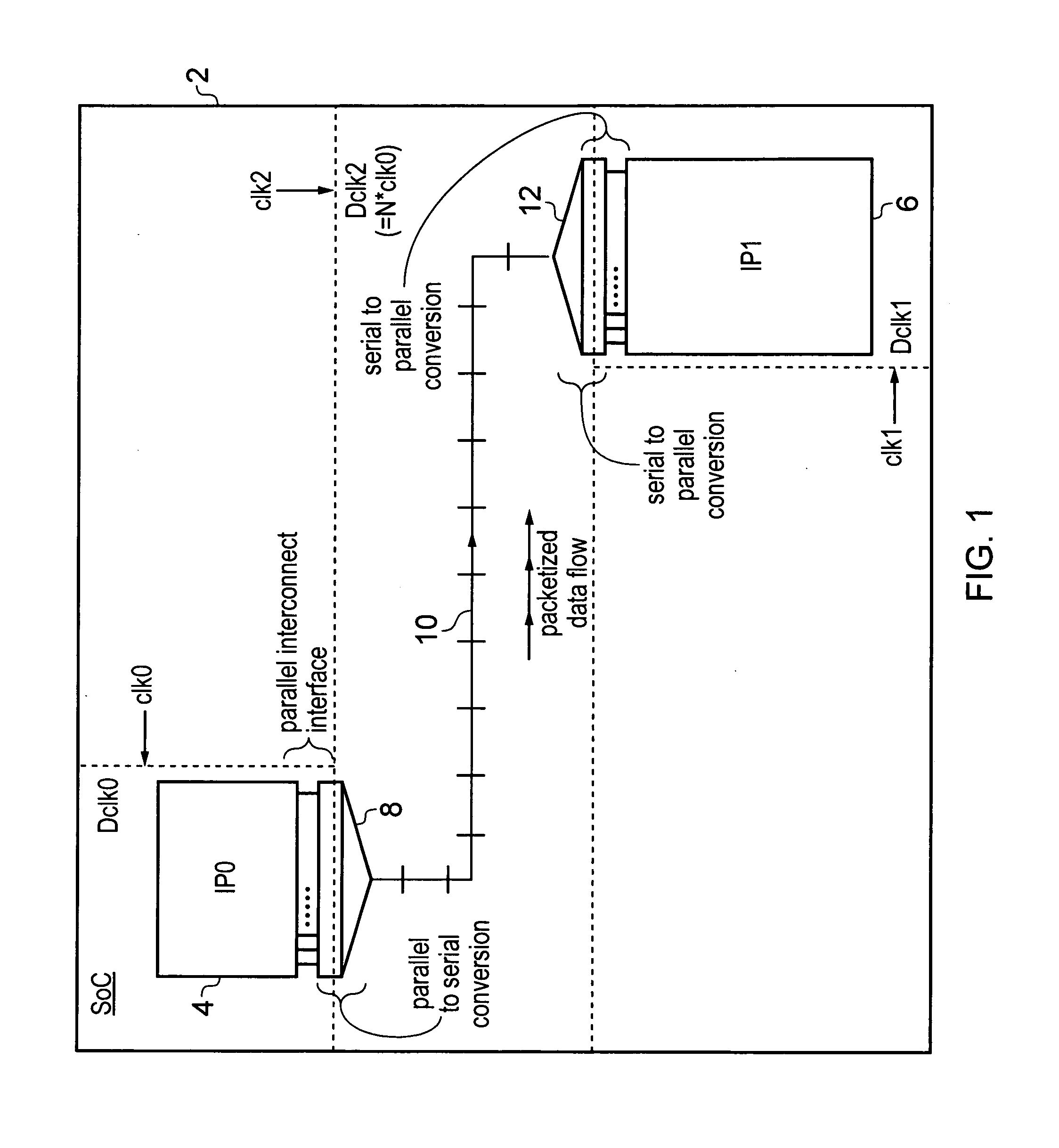
[0071]FIG. 1 schematically illustrates a system-on-chip integrated circuit 2 including a source functional block 4 and a destination functional block 6 between which it is desired to pass signals. The source functional block 4 and the destination functional block 6 can take a variety of different forms, e.g. a processor core, a graphics processing unit, a memory controller, an input / output controller, a memory controller etc. Such functional blocks 4, 6 are conventionally provided with a parallel interconnect interface, such as an AXI interface as designed by ARM Limited of Cambridge, England. Such a parallel interconnect interface is wide and may include several hundred bit line signals. In order to efficiently transfer the signals from this wide parallel interconnect interface across the system-on-chip integrated circuit, the present technique uses parallel-to-serial conversation which converts the parallel interconnect interface signals into a plurality of data packets. This conv...
PUM
 Abstract
Description
Claims
Application Information