Device for Purifying Oily Wastewater

a technology for purifying devices and wastewater, applied in the nature of treatment water, multi-stage water/sewage treatment, separation processes, etc., can solve the problems of difficult to meet the technology requirements for purifying produced water enriched with emulsified oil and suspended solids, affecting the oil yield of oilfields, and affecting the flow speed of produced water, etc., to achieve the effect of strong turbulence of wastewater, negative influence on flocculation, and gradual reduction of flow speed

Inactive Publication Date: 2013-03-14
BEIJING OTC ENERGY & ENVIRONMENT ENGINEERING PUBLIC LIMITED COMPANY
View PDF1 Cites 15 Cited by
  • Summary
  • Abstract
  • Description
  • Claims
  • Application Information

AI Technical Summary

Benefits of technology

[0011]The internal structure of the device in the present application is designed precisely based on the coagulation mechanism. When wastewater added with agent(s) is injected to the bottom of the cylindrical central coagulation reaction tube along a tangent direction, the flow direction of the wastewater is changed significantly due to the particular structure of the cylindrical body of the central coagulation reaction tube. Due to the additional agitation of the agitator, a relatively strong turbulence of the wastewater occurs so that the agent is sufficiently mixed with the wastewater. At this point, sludge particles in the wastewater are within the initial flocculation stage, and the turbulence has an insignificant influence on the flocculation. As the flocculation proceeds, the sludge particles are getting bigger. As the sludge flocculation proceeds to the late flocculation stage, the turbulence has a more and more negative influence on the flocculation. At this point, in favor of the demand of flocculation process, the mixture of the agent and wastewater flows into the reverse cone-shaped cyclone flocculation stage, where the section is getting larger, the flow speed is gradually reduced, and the flowage of the mixture is alleviated. Thus, the flocculation action is substantially completed at the little bottom of the reverse cone-shaped cyclone flocculation stage. The sludge particles after the flocculation have a density that is getting larger as the sludge particles rise, while the flow speed of the mixture is getting lower. Subsequently, sludge particles that are gradually sedimentated are supported and pressed by the rising flow of wastewater continuously inputted from the lower portion of the vertical tank; as a result, the sludge remains stationary when its gravity is equal to the applied support and pressing forces, thereby forming a filtering layer of suspended sludge at the suspended sludge filtering zone. Particles in the filtering layer of suspended sludge are getting bigger as the filtering layer intercepts contaminants carried by the incoming water, and thus have an increasing sedimentation speed, so that the rising speed of water flow and water yield can be improved, and the filtration effect can be achieved.
[0012]The dense filtering layer of suspended sludge is composed of flocs formed from both the suspended solid carried in the wastewater and the coagulant. The lower surface layer of the filtering layer grows thicker increasingly as the flocs move upwards. Further, as a bypass in the tank caused by the filtered water according to hydraulic mechanism flows, sludge of the upper surface layer of the filtering layer of suspended sludge is guided continuously into the peripheral sludge collecting groove, so that the upper surface layer is continuously reduced and gets thinner, and the thickness of the filtering layer of suspended sludge reaches a homeostasis. When the wastewater subjected to the coagulation goes upwards through the filtering layer of suspended sludge, i.e. a filtering layer of flocs, contaminants such as suspended colloid particles, flocs and bacteria thalluses are intercepted within the filtering layer of suspended sludge due to combined forces of interfacial physical adsorption and netting catch, electrochemical characteristics of the filtering layer of flocs, an effect of Van der Waals forces, as well as an effect of mechanical filtration, so that the resultant water has a quality as high as that of water produced from fine filtration. The filtering layer of suspended sludge, which is composed of the flocs and has a high density, has a filtering efficiency fairly higher than that of the conventional filtering using a sand layer. Also, the filtering layer of suspended sludge has a very low head loss (i.e., resistance) caused by the filtration, because it is formed of the suspended sludge, and therefore has a head loss fairly less than that of the conventional filtering using the sand layer, the filtering using micropores or the filtering using a reverse osmosis membrane. Further, the filtering layer of sludge is automatically supplemented by the suspended solid carried in the wastewater during the purification process in addition to being reduced automatically, that is, the filtering layer of sludge is updated continuously, thus maintaining a stable thickness and stable physical and electrochemical absorption capabilities, thereby achieving a stable filtering effect, and eliminating a backwashing process of the filtering material layer and updating and supplementing of filtering materials that are essential in the conventional filtering system.
[0013]The device disclosed in the application is advantageous in that oily wastewater is sequentially subjected to the coagulation reaction and the processes of suspended sludge purification and purified water commutation, by means of the internal structure of the device, so that the purification reaction, flocculation and fine filtration of wastewater and the sludge concentration process are implemented integrally within the tank body of the same device for purifying wastewater. Therefore, the device described in the present application has advantages such as a simple but reliable purification process, low investment and operation costs, low land occupation, less restrict requirements on the wastewater, an improved purification efficiency, and elimination of backwashing of the filtering material layer and pollution of filtering materials, thereby providing a novel way applicable to the reinjection of oilfield produced water and the purification treatment of wastewater of petrochemical enterprises, as well as invaluable social benefits and economical benefits.

Problems solved by technology

The oil yield of the oilfield is affected if the wastewater containing a considerable amount of contaminants such as suspended solid and emulsified oil is reinjected underground.
The traditional technologies and equipment for the treatment of wastewater with the use of two-stage sedimentation and two-stage filtration have drawbacks of a long purification process, a large system and a low purification efficiency, and thus are difficult to satisfy technology requirements for purifying the produced water enriched with emulsified oil and suspended solid.
Further, the traditional technology system for the treatment of oily wastewater is disadvantageous for a low efficiency and unstable operations.
Wastewater treatment technology using a ceramic ultrafiltration membrane has been studied since 1991, but is still within the industrial trial stage due to the high price of the ceramic membrane, strict pretreatment requirements and strict requirements on the cleaning of the membrane.
In addition, the deoiling technology using a cyclone, although being advantageous for simple facilities and low costs, cannot obtain water qualified for the reinjection from the treatment of the produced water.

Method used


Image

  • Device for Purifying Oily Wastewater
  • Device for Purifying Oily Wastewater

Examples


Embodiment Construction

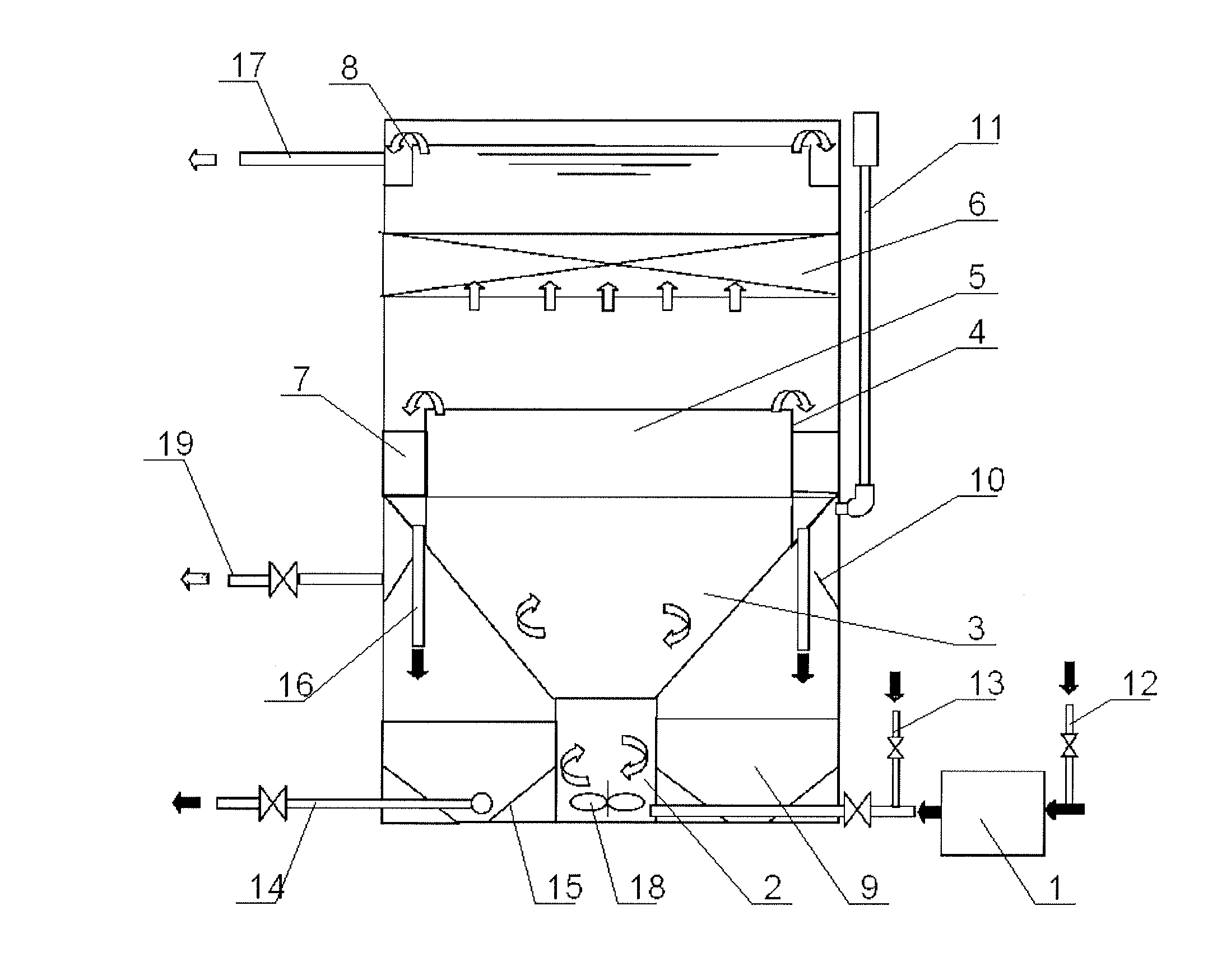
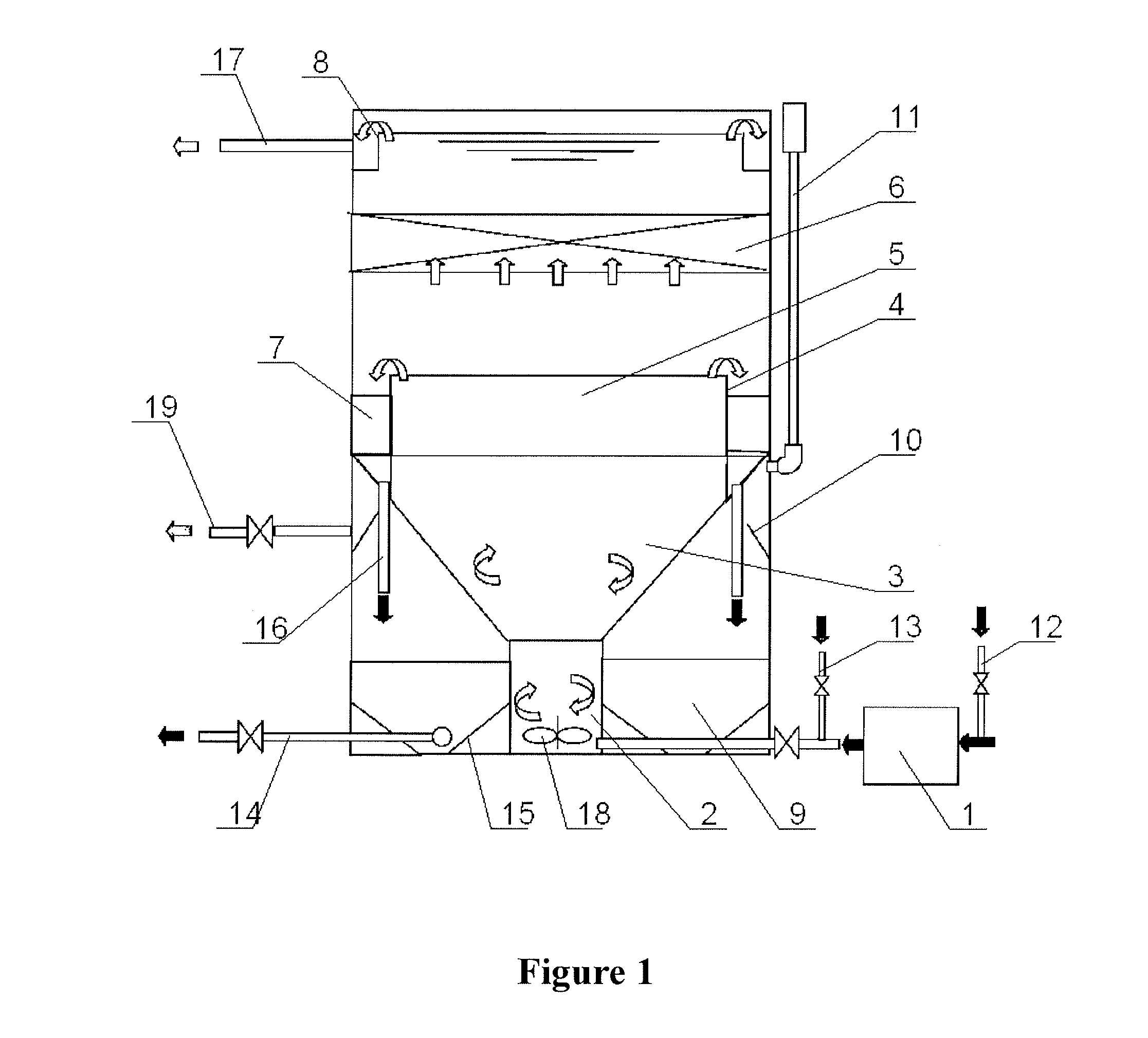
[0035]As shown in FIG. 1, a device for purifying oily wastewater according to an embodiment of the invention includes a vertical tank of an atmospheric pressure, inside which a central coagulation reaction tube 2, a reverse cone-shaped cyclone flocculation stage 3, a suspended sludge filtering zone 5 and a purified water commutation stage of inclined plates 6 are included from bottom to top sequentially. The central coagulation reaction tube 2 is provided with a wastewater inlet at its bottom along a tangent direction. Also, at the bottom of the central coagulation reaction tube 2, an agitator having an adjustable rotation speed is provided, and the rotation speed may be set depending upon properties of the oily wastewater for achieving an optimal mixing effect.

[0036]A weir plate 4 is installed peripherally around the suspended sludge filtering zone 5, thereby forming sludge collecting groove(s) 7 which are in communication with a sludge concentrating zone 9 via sludge overflow pipe...


PUM

PropertyMeasurementUnit
atmospheric pressureaaaaaaaaaa
rotation speedaaaaaaaaaa
structureaaaaaaaaaa

Abstract

There is disclosed a device for purifying oily wastewater, including a vertical tank of an atmospheric pressure, inside which a central coagulation reaction tube, a reverse cone-shaped cyclone flocculation stage, a suspended sludge filtering zone and a purified water commutation stage of inclined plates are included from bottom to top sequentially, oily wastewater is sequentially subjected to a coagulation reaction, suspended sludge filtering and a purified water commutation process and then discharged, a sludge collecting groove collects and guides the suspended sludge to a sludge concentrating zone for further sedimentation and concentration processes and then discharges it to external to the tank, in this way, the purification reaction, flocculation and fine filtration of wastewater and the sludge concentration process are integrated within the same wastewater purifying device. Thus, the device is equivalent to the existing wastewater pretreatment system plus a fine filtration system.

Description

FIELD OF THE INVENTION[0001]The present application relates to the field of oily wastewater treatment technologies, and particularly, to a device for purifying oily wastewater that is applicable to oilfield reinjection and petrochemical enterprises.BACKGROUND OF THE INVENTION[0002]At present, a way of exploitation by means of water injection is mostly adopted in the oilfield, and water of about 5-8 m3 is reinjected underground for exploiting every one ton of crude oil. Produced water of the oilfield is almost entirely reinjected underground after being treated. The oil yield of the oilfield is affected if the wastewater containing a considerable amount of contaminants such as suspended solid and emulsified oil is reinjected underground. Therefore, technologies and equipment for treating oilfield wastewater for reinjection are essential to the exploitation and production of the oilfield.[0003]The traditional technologies and equipment for the treatment of wastewater with the use of t...

Claims


Application Information

Patent Timeline
Patent Type & Authority Applications(United States)
IPC IPC(8): C02F11/00
CPCB01D21/0012B01D21/0045B01D21/0084B01D21/08B01D21/2411B01D21/245B01D21/2483B01D21/2494B01D21/01C02F1/001C02F1/24C02F1/40C02F1/52C02F2103/10C02F2103/365C02F2301/026
Inventor JIANG, XUEWENZHANG, YUKAIWU, YANGSHAN
Owner BEIJING OTC ENERGY & ENVIRONMENT ENGINEERING PUBLIC LIMITED COMPANY
Why Eureka
Try Eureka