Movable structure, and deflection mirror element, optical switch element and shape variable mirror including the movable structure

Active Publication Date: 2005-04-19
OLYMPUS CORP
View PDF5 Cites 20 Cited by
  • Summary
  • Abstract
  • Description
  • Claims
  • Application Information

AI Technical Summary

Benefits of technology

[0017]According to the movable structure of the present invention, since the elastic member has the mesh structure, the stress generated inside the elastic member is eased, and abnormal deformation of the elastic member is prevented from being generated. As a result, there are provided a movable structure for a micromachine element, the movable structure avoiding deterioration in the impact resistance of the micromachine element such as generation of abnormal deformation of the spring, while achieving improvement in the drive efficiency and reduction in the non-linearity of the drive characteristic, and a micromachine element, such as a deflection mirror element, an optical switch element and a shape variable mirror, including the movable structure.

Problems solved by technology

However, such a slender and thin spring disadvantageously considerably lowers the impact resistance of the micromachine element.
In the micromachine element (deflection mirror element) having such a flexuous structure springs, however, when an impact shock is given to the micromachine element, abnormal deformation may be possibly generated in the flexuous structure springs.

Method used


Image

  • Movable structure, and deflection mirror element, optical switch element and shape variable mirror including the movable structure
  • Movable structure, and deflection mirror element, optical switch element and shape variable mirror including the movable structure
  • Movable structure, and deflection mirror element, optical switch element and shape variable mirror including the movable structure

Examples


first embodiment

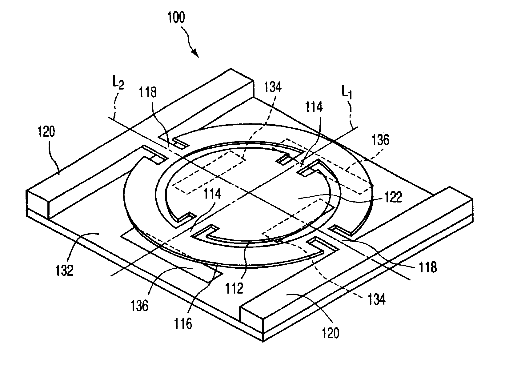
[0046]As a first embodiment of the present invention, FIG. 1 shows an optical deflection element having a movable structure according to the present invention.

[0047]The optical deflection element comprises a movable structure and a substrate 132 supporting the movable structure. The movable structure comprises an inner movable plate 112, an outer movable plate 116 corresponding the inner movable plate 112, a pair of torsion springs 114 connecting the inner movable plate 112 and the outer movable plate 116, a pair of supports 120 positioned outside the outer movable plate 116, and a pair of torsion springs 118 connecting the outer movable plate 116 and the supports 120.

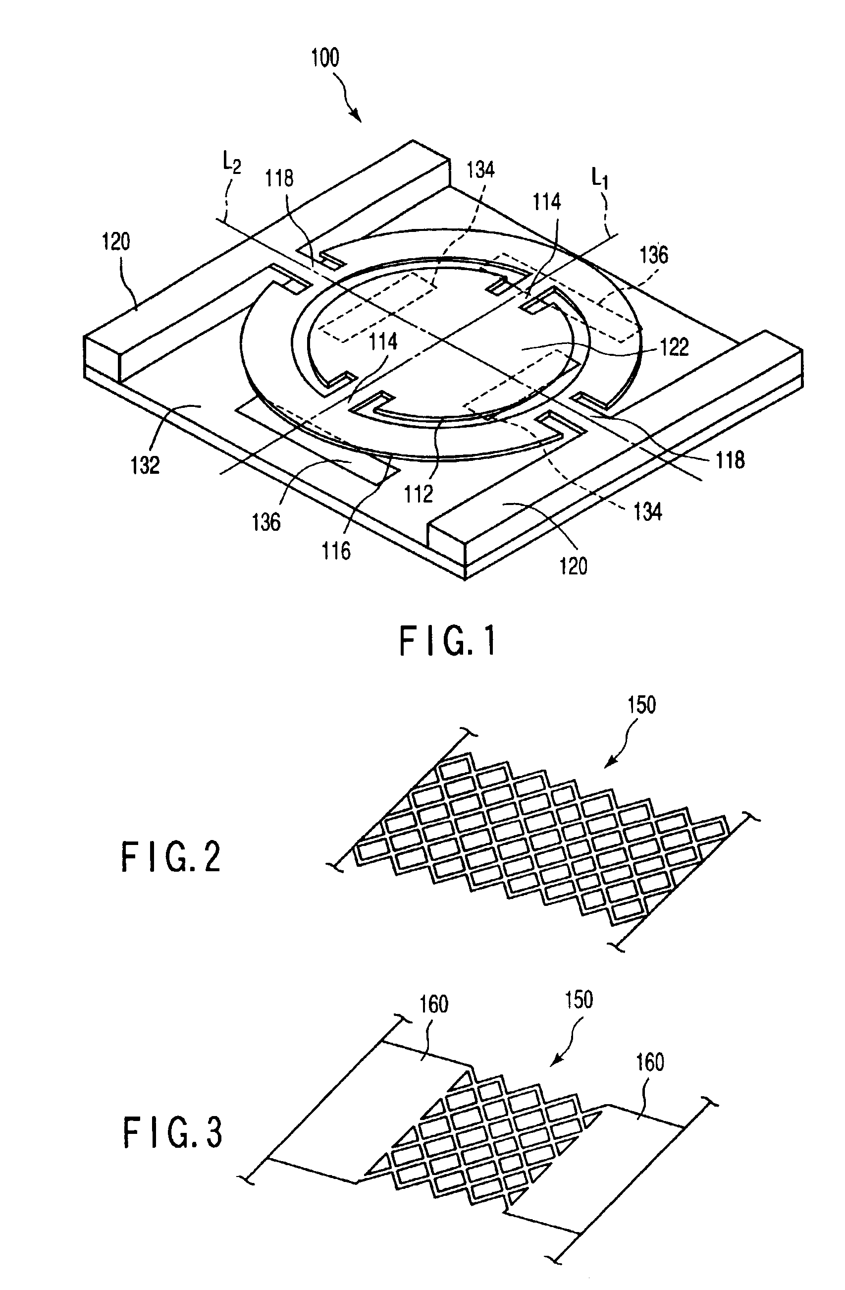
[0048]Both the inner torsion spring 114 and the outer torsion spring 118 at least partially have the mesh structure. For example, as shown in FIG. 2, the inner torsion spring 114 and the outer torsion spring 118 are entirely constituted by the mesh structure 150. Alternatively, as shown in FIG. 3, the inner torsion spr...

second embodiment

[0066]As a second embodiment according to the present invention, FIG. 6 shows an optical switch element having a movable structure according to the present invention.

[0067]The optical switch element 200 comprises a movable structure and a substrate 232 supporting the movable structure. The movable structure comprises a rectangular movable plate 212, four supports 216 positioned around the movable plate 212 with respect to each side of the movable plate 212, and four support springs 214 connecting each side of the movable plate 212 and each of the supports 216.

[0068]The support spring 214 at least partially has a mesh structure. For example, as shown in FIG. 2, the support spring is entirely constituted by the mesh structure 150. Alternatively, as shown in FIG. 3, the support spring 214 partially has the mesh structure 150. That is, the support spring 214 has the mesh structure 150 and the platy portion 160.

[0069]The movable plate 212 is allowed to move so as to be closer to the subs...

third embodiment

[0082]As a third embodiment according to the present invention, FIG. 7 shows a shape variable mirror having the movable structure according to the present invention.

[0083]The shape variable mirror 300 includes a movable structure and a substrate 332 supporting the movable structure. The movable structure comprises a deformable elastic film 312 having a reflection surface, a pair of supports 316 positioned on the both sides of the elastic film 312, and a pair of support springs 314 connecting the elastic film 312 and the support 316.

[0084]The support springs 314 at least partially have the mesh structure. For example, as shown in FIG. 2, each of the support spring 314 is entirely constituted by the mesh structure 150. Alternatively, as shown in FIG. 3, the support spring 314 partially has the mesh structure 150. That is, the support spring 314 has the mesh structure 150 and a platy portion 160.

[0085]The substrate 332 has electrodes 334 opposed to the elastic film 312. A metal film 31...


PUM


Abstract

There is disclosed a movable structure, which includes a movable body, at least a pair of elastic members extending from the movable body to both sides, and a support supporting the movable body through the elastic members, each elastic member having a mesh structure, and the support and the movable body being connected to each other through the elastic members.

Description

CROSS-REFERENCE TO RELATED APPLICATIONS[0001]This application is based upon and claims the benefit of priority from the prior Japanese Patent Applications No. 2001-285571, filed Sep. 19, 2001; and No. 2002-62457, filed Mar. 7, 2002, the entire contents of both of which are incorporated herein by reference.BACKGROUND OF THE INVENTION[0002]1. Field of the Invention[0003]The present invention relates to a movable structure having a movable body allowed to move with respect to a support, and more particularly to a movable structure manufactured by a micromachine manufacturing process or the like.[0004]2. Description of the Related Art[0005]In a micromachine element, a movable structure having a movable body supported by a pair of springs is often used. FIG. 22 shows this movable structure. As shown in FIG. 22, the movable structure 700 comprises a movable body 712, supports 716, and springs each of which connects the movable body 712 and the support 716. The movable body 712 is allowed ...

Claims


Application Information

Patent Timeline
IPC IPC(8): G02B26/08
CPCG02B26/0841
Inventor ARIMA, MICHITSUGU
Owner OLYMPUS CORP
Why Eureka
Try Eureka