
Disk drive device provided with fluid dynamic bearing

a technology of fluid dynamic bearing and drive device, which is applied in the direction of record information storage, record carrier contruction details, instruments, etc., can solve the problems of impact affecting all these narrow gaps, failure in practical use, and deterioration of the impact resistance performance of the drive device, so as to achieve the effect of impact resistance when dropped

Inactive Publication Date: 2012-08-14
SAMSUNG ELECTRO MECHANICS JAPAN ADVANCED TECHNOLOGY CO LTD
View PDF10 Cites 10 Cited by
  • Summary
  • Abstract
  • Description
  • Claims
  • Application Information

AI Technical Summary

Benefits of technology

"The present invention provides a disk drive device with improved impact resistance. This is achieved by improving the design of the device's components, including the tubular sleeve, housing member, base member, hub, and thrust member. The invention also includes the use of a concave-shaped area to retain redundant adhesive, the filling of a lubricant between the housing member and thrust member, and the use of a protrusion to protect the shaft. These technical features enhance the device's ability to withstand impacts and improve its overall performance."

Problems solved by technology

As a result, the impact resistant performance thereof is deteriorated, creating a trade-off requirement.
However, considering impact situations in the present mobile devices, there may occur a failure in practical use, if the disk drive device does not withstand 800 G as the maximum impact for a short time, for example, 1 ms.
In particular, the disk drive device provided with a fluid dynamic bearing is configured such that fixed bodies and rotating bodies face each other in several narrow gaps, and hence an impact affects all these narrow gaps.
Accordingly, there occur many types of failures due to the impact, requiring comprehensive technical innovation to be developed because those cannot be solved by a single technical innovation.
A first type of failures occurs due to deformation of a component itself.
In the disk drive device into which the fluid dynamic bearing or the like is accurately incorporated so as to be slightly spaced apart, the deformation of the component causes a malfunction in the entire disk drive device.
The joint portion is likely to cause stress concentration and has a low strength in comparison with that of the integral portion, and therefore deformation or destruction by a stress due to an impact acceleration occurs, causing the disk drive device to be in a malfunction.
However, scattering of the lubricant by the impact acceleration causes shortage of the lubricant, thereby the disk drive device being in a malfunction such as burn-in of a bearing, in a short time.
The scraped powder enters the gap of the fluid dynamic bearing and promotes the wearing thereof, causing the fluid dynamic bearing to be in a malfunction such as burn-in of a bearing in a short time.

Method used


Image

  • Disk drive device provided with fluid dynamic bearing
  • Disk drive device provided with fluid dynamic bearing
  • Disk drive device provided with fluid dynamic bearing

Examples


Embodiment Construction

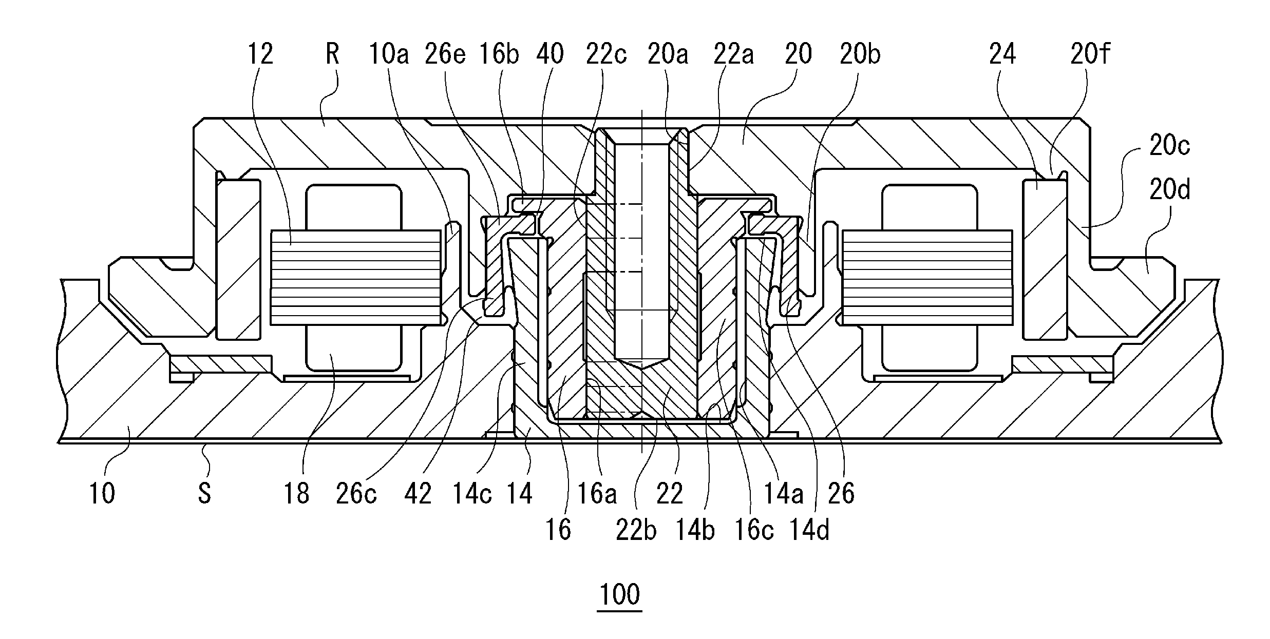
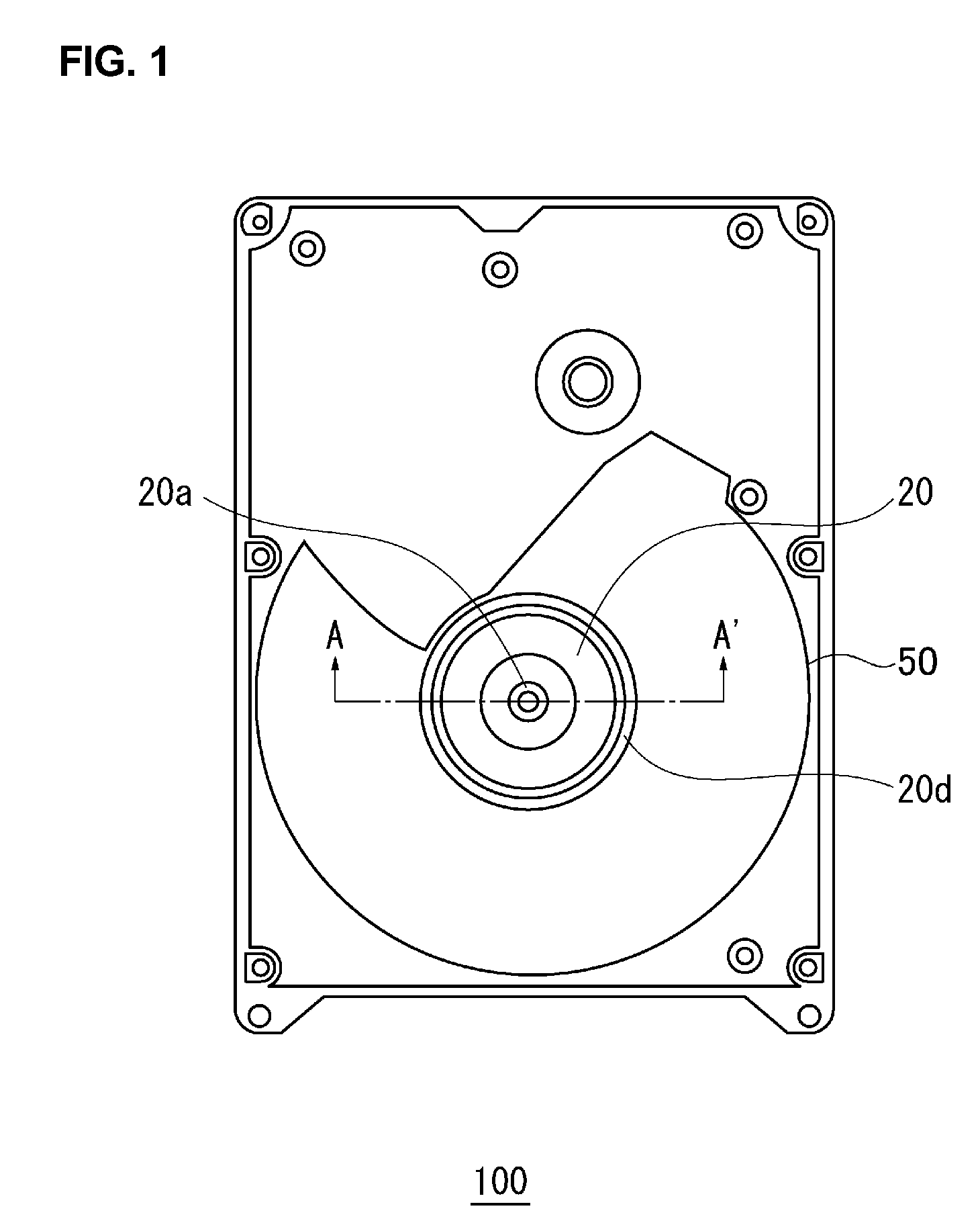
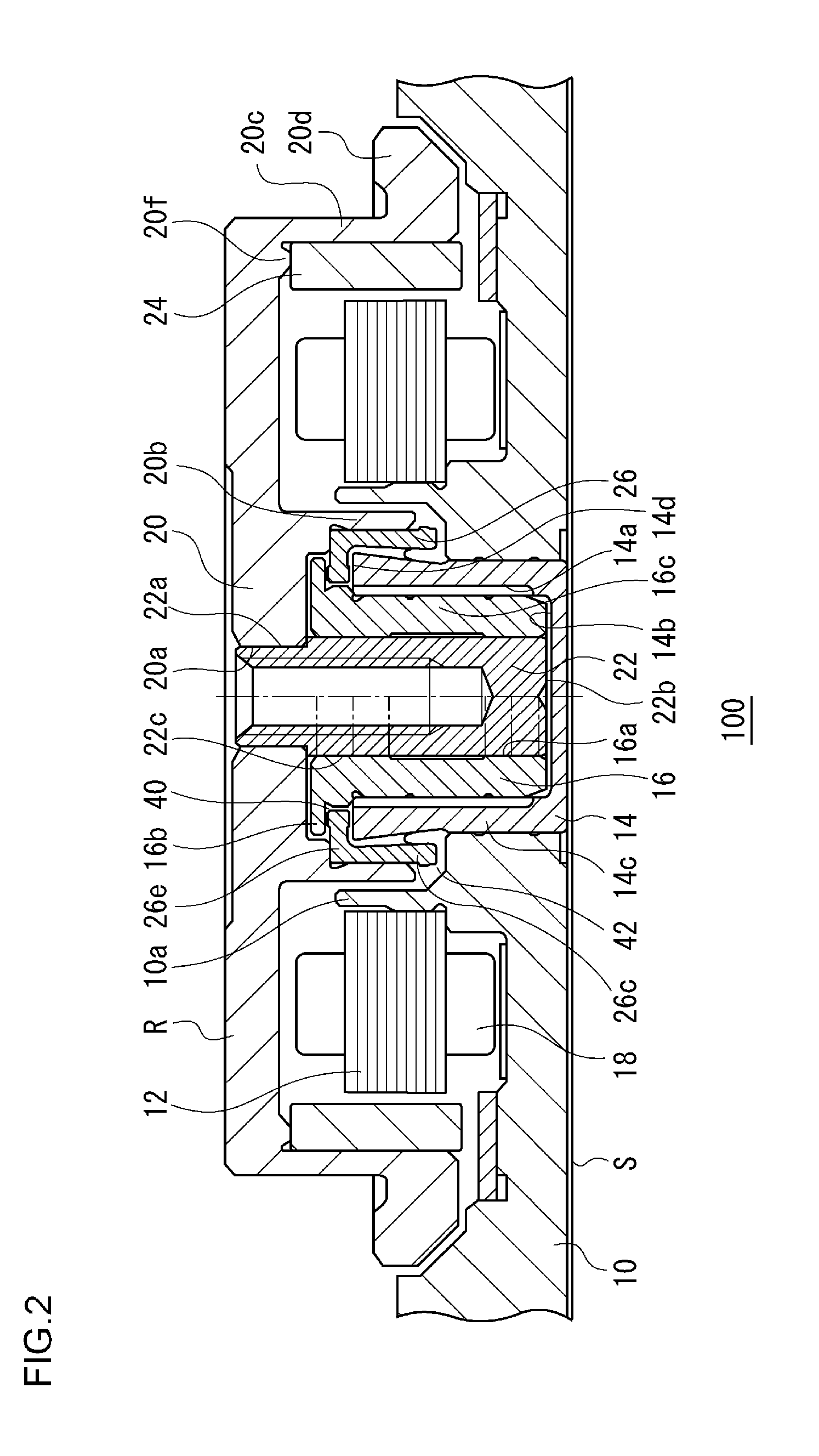
[0035]The invention will now be described by reference to the preferred embodiments. This does not intend to limit the scope of the present invention, but to exemplify the invention. An embodiment of the present invention is a disk drive device that is mounted in a hard disk drive and used for driving a magnetic recording disk, and a rotation speed thereof is, for example, 5400 rpm. Hereinafter, the same or equivalent constituting elements and members illustrated in each drawing shall be denoted by the same reference numerals, and the duplicative explanations will be omitted appropriately. Dimensions of members illustrated in each drawing are appropriately enlarged or reduced for easier understanding. Part of members not important for describing the embodiment are omitted from each drawing.

[0036]FIG. 1 is a top view illustrating the structure of a disk drive device 100 according to an embodiment of the present invention. The disk drive device 100 includes a hub 20, which is formed i...


PUM

PropertyMeasurementUnit
diameteraaaaaaaaaa
distanceaaaaaaaaaa
thicknessaaaaaaaaaa

Abstract

A sleeve supports a shaft. A housing member is arranged so as to surround the sleeve and make the end of the sleeve protrude. A base member holds the housing member and fixes a stator core so as to surround the housing member. A hub drives a recording disk by being rotated integrally with the shaft, with a magnet being fixed to an annular portion concentric with the shaft so as to face the stator core fixed to the base member. A thrust member is rotated integrally with the hub, and a descender portion and a ring portion.

Description

CROSS-REFERENCE TO RELATED APPLICATIONS[0001]This application is based upon and claims the benefit of priority from the prior Japanese Patent Application No. 2009-020953, filed on Jan. 30, 2009, and Japanese Patent Application No. 2009-020954, filed on Jan. 30, 2009, the entire contents of which are incorporated herein by reference.FIELD OF THE INVENTION[0002]The present invention relates to a disk drive device, and in particular, to a disk drive device provided with a fluid dynamic bearing.DESCRIPTION OF THE RELATED ART[0003]Recently, a disk drive device such as a Hard Disk Drive (HDD) has been dramatically improved in its rotational accuracy by providing a fluid dynamic bearing, allowing the device with high density and large capacity. Due to this, a disk drive device provided with a fluid dynamic bearing has been mounted in a wide variety of apparatuses. Accordingly, the disk drive device has been used in various environments. In particular, the device has been increasingly mount...

Claims


Application Information

Patent Timeline
Patent Type & Authority Patents(United States)
IPC IPC(8): G11B17/02F16C32/06
CPCF16C33/107G11B19/2036H02K5/1675G11B33/02F16C33/745F16C17/107F16C2370/12
Inventor YAMADA, TAKUJIOMURA, YUJIKODAMA, MITSUO
Owner SAMSUNG ELECTRO MECHANICS JAPAN ADVANCED TECHNOLOGY CO LTD
Learn More