Wooden post protective sleeve

a protective sleeve and wood technology, applied in the direction of machine supports, other domestic objects, mechanical apparatus, etc., to achieve the effects of low manufacturing cost, convenient and efficient manufacturing and marketing, and durable and reliable construction

Inactive Publication Date: 2005-05-03
JOHN MICHAEL +1
View PDF25 Cites 131 Cited by
  • Summary
  • Abstract
  • Description
  • Claims
  • Application Information

AI Technical Summary

Benefits of technology

[0012]It is therefore an object of the present invention to provide a new and improved wooden post protective sleeve which has all the advantages of the prior art support devices for ground anchors and none of the disadvantages.
[0013]It is another object of the present invention to provide a new and improved wooden post protective sleeve which may be easily and efficiently manufactured and marketed.
[0014]It is a further object of the present invention to provide a new and improved wooden post protective sleeve which is of durable and reliable construction.
[0015]An even further object of the present invention is to provide a new and improved wooden post protective sleeve which is susceptible of a low cost of manufacture with regard to both materials and labor, and which accordingly is then susceptible of low prices of sale to the consuming public, thereby making such a wooden post protective sleeve economically available to the buying public.
[0016]Even still another object of the present invention is to provide a new and improved wooden post protective sleeve for protecting a lower end of a wooden post from rotting while positioned within a hole in a ground area while also making insertion into and removal from the hole easier.

Problems solved by technology

While these devices fulfill their respective, particular objective and requirements, the aforementioned patents do not describe a wooden post protective sleeve for protecting a lower end of a wooden post from rotting while positioned within a hole in a ground area while also making insertion into and removal from the hole easier.

Method used


Image

  • Wooden post protective sleeve
  • Wooden post protective sleeve
  • Wooden post protective sleeve

Examples


Embodiment Construction

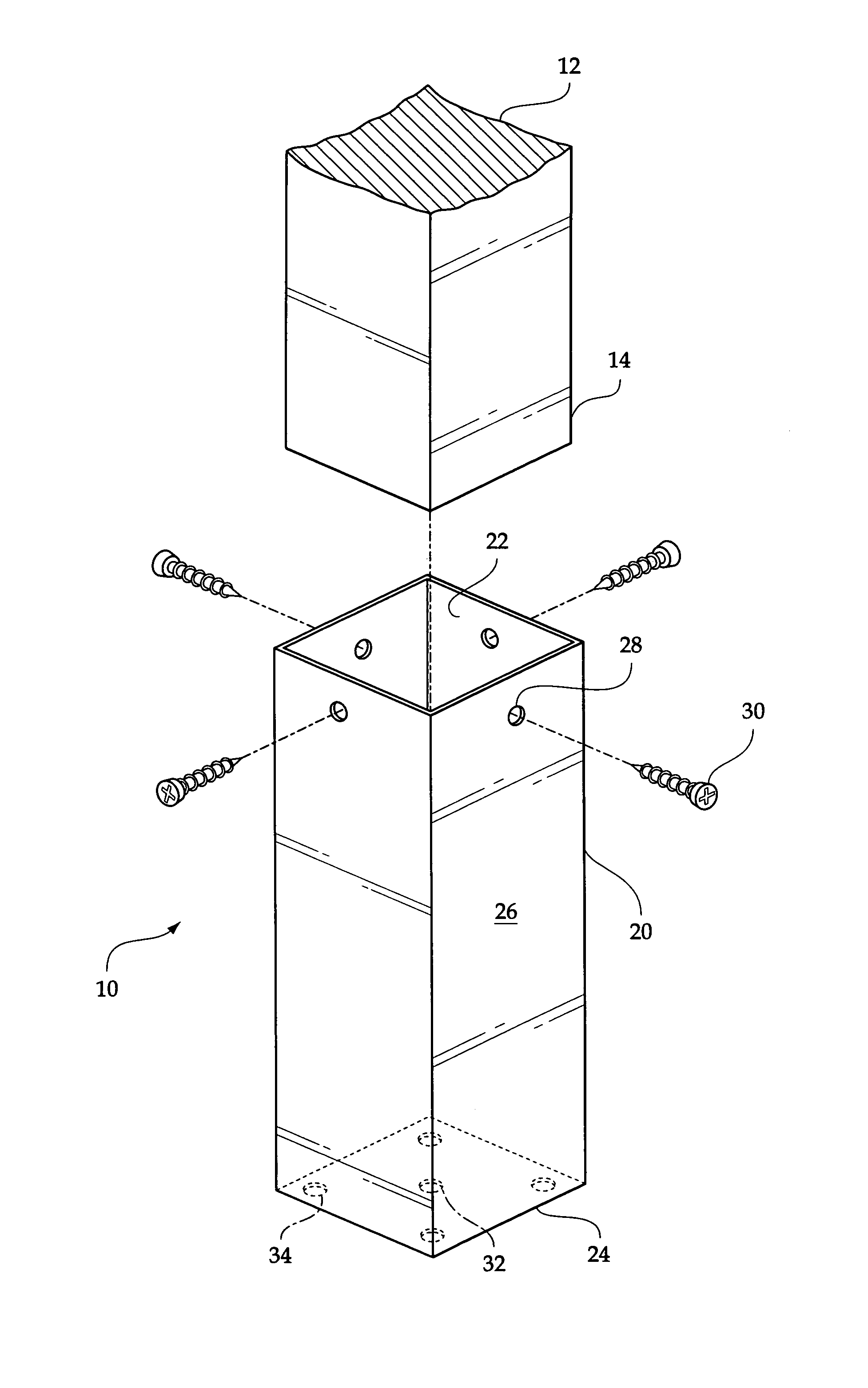
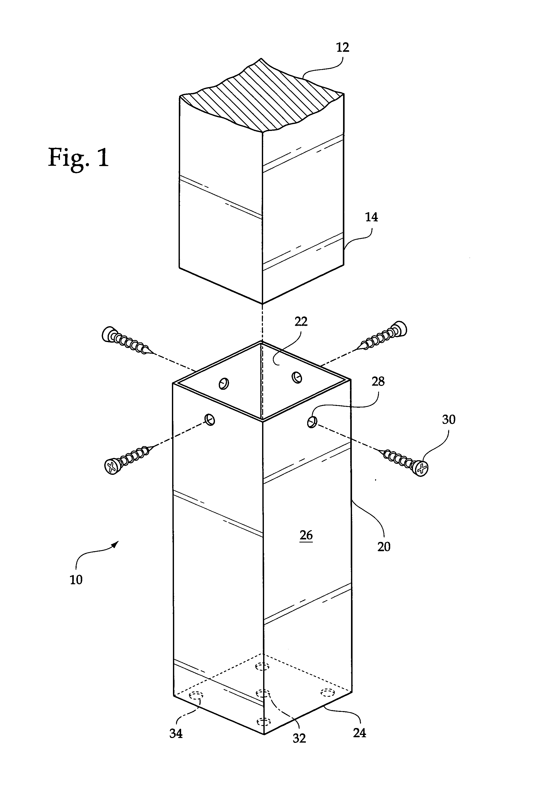
[0024]With reference now to the drawings, and in particular, to FIGS. 1 through 3 thereof, the preferred embodiment of the new and improved wooden post protective sleeve embodying the principles and concepts of the present invention and generally designated by the reference number 10 will be described.

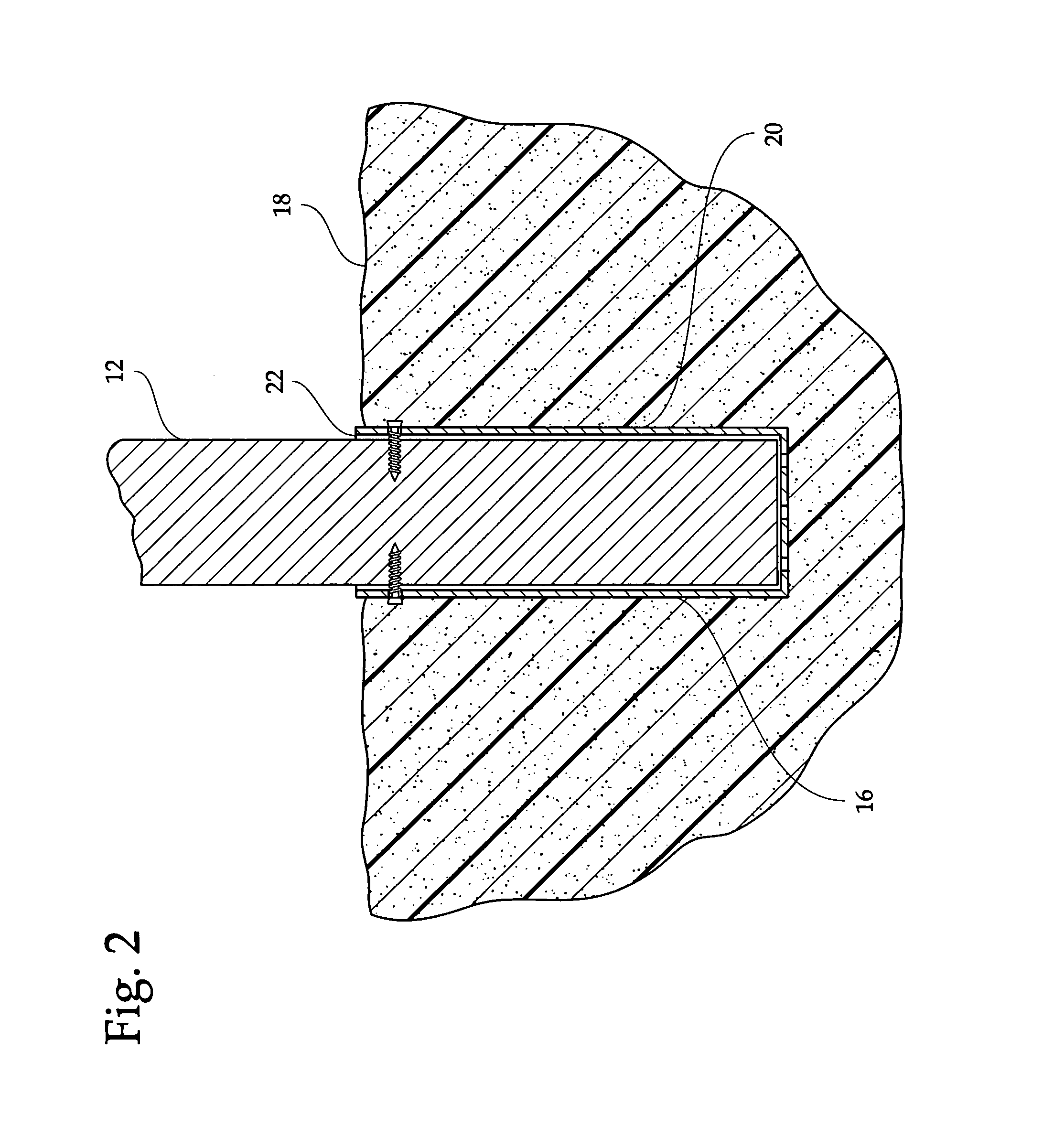
[0025]Specifically, it will be noted in the various figures that the device relates to a wooden post protective sleeve for protecting a lower end of a wooden post from rotting while positioned within a hole in a ground area while also making insertion into and removal from the hole easier.

[0026]The present invention is designed for use with a wooden post 12 that has a lower end 14 that is ordinarily positioned within a hole 16 that has been dug in a ground area 18. An upper end of the wooden post 12 normally supports an item, such as a mailbox, thereon. The wooden post 12 could also be a single component of a plurality of posts used to make up a fence.

[0027]The present invention is ess...


PUM


Abstract

A wooden post protective sleeve including a collar having an open upper end, a closed lower end, and a surrounding side wall. The open upper end is dimensioned for receiving the lower end of the wooden post therein. The surrounding side wall has a plurality of apertures therethrough downwardly of the open upper end. The apertures are dimensioned for receiving wood screws therethrough for engaging the lower end of the wooden post. The closed lower end has a plurality of drainage apertures therethrough. The drainage apertures include a central aperture and four peripheral apertures. The collar is fabricated of plastic.

Description

BACKGROUND OF THE INVENTION[0001]The present invention relates to a wooden post protective sleeve and more particularly pertains to protecting a lower end of a wooden post from rotting while positioned within a hole in a ground area while also making insertion into and removal from the hole easier.[0002]The use of support devices for ground anchors is known in the prior art. More specifically, support devices for ground anchors heretofore devised and utilized for the purpose of providing support to ground anchors are known to consist basically of familiar, expected and obvious structural configurations, notwithstanding the myriad of designs encompassed by the crowded prior art which have been developed for the fulfillment of countless objectives and requirements.[0003]By way of example, U.S. Pat. No. 5,203,817 to Klumpjan discloses a fence post bracket capable of holding the post above ground level to provide complete drainage and minimize deterioration. U.S. Pat. No. 5,720,134 to K...

Claims


Application Information

Patent Timeline
Patent Type & Authority Patents(United States)
IPC IPC(8): E02D5/60E02D5/22
CPCE04H12/2292E02D5/60
Inventor JOHN, MICHAELJOHN, SHARIANNE
Owner JOHN MICHAEL
Why Eureka
Try Eureka