Recording apparatus

Inactive Publication Date: 2005-05-31
CANON KK
View PDF15 Cites 47 Cited by
  • Summary
  • Abstract
  • Description
  • Claims
  • Application Information

AI Technical Summary

Benefits of technology

[0020]According to the present invention, a recording apparatus for recording on a recording material by recording means, includes: a carriage having the recording means mounted thereon and moving in a direction crossing a recording material transporting direction; a guide shaft for guiding a movement of the carriage; and guide shaft lifting and lowering means for changing a position in height of the guide shaft at three or more stages without changing a position of the guide shaft in the recording material transporting direction. Consequently, a recording apparatus can be provided, in which the guide shaft can be lifted and lowered to the three or more positions in height without changing the position of the guide shaft in the recording material transporting direction, so that the high-quality recording at the accurate position on the recording material can be readily performed even if the control for changing a recording start position to the recording material is omitted.
[0021]Also, according to the present invention, a recording apparatus for recording on a recording material by recording means, includes: a carriage having the recording means mounted thereon and moving in a direction crossing a recording material transporting direction; a guide shaft for guiding a movement of the carriage; and guide shaft lifting and lowering means for changing a position in height of the guide shaft at three or more stages, in which the carriage regulates a state of the guide shaft lifting and lowering means to thereby regulate at least one position in height of the guide shaft. Consequently, a recording apparatus including the guide shaft lifting and lowering means can be provided, with which an operation for lifting and lowering the guide shaft to the plural positions in height without changing the posi

Problems solved by technology

In the existing general-purpose recording apparatuses, assuming that a transport path for cut paper is adapted for recording on the recording material such as CD, the following defects are caused due to high rigidity of the CD.
That is, a transport property is lowered, any scratch develops, or transport cannot be made due to problems concerning a distance between transport rollers.
(a) As shown in FIGS. 32A and 32C, the eccentric cams 524 at both ends of the guide shaft 52 are rotated to lift or lower the guide shaft vertically by the operation lever. At this time, when the print height is changed to two levels, i.e., general print height of the carriage and uppermost print height thereof, the position of the guide shaft 52 in the recording material transporting direction, that is, the position of the carriage in the recording material transporting direction is not changed. However, as shown in FIG. 32B, the print height is changed to intermediate print height, the position of the carriage in the recording material transporting direction is changed. As a result, a recording start position to the recording material should be changed for accurate recording, which leads to a complicated control.
(b) The guide shaft 52 is supported to a main body chassis through the eccentric cams 524 at both ends. Thus, parallelism of the transport roller for transporting the recording material and the guide shaft which are similarly supported to the main body chassis is lowered to some extent corresponding to an involved part tolerance in the case of supporting the guide shaft through the eccentric cams as compared with the case where the guide shaft is directly fixed to the main

Method used


Image

  • Recording apparatus
  • Recording apparatus
  • Recording apparatus

Examples


embodiment 1

(Embodiment 1)

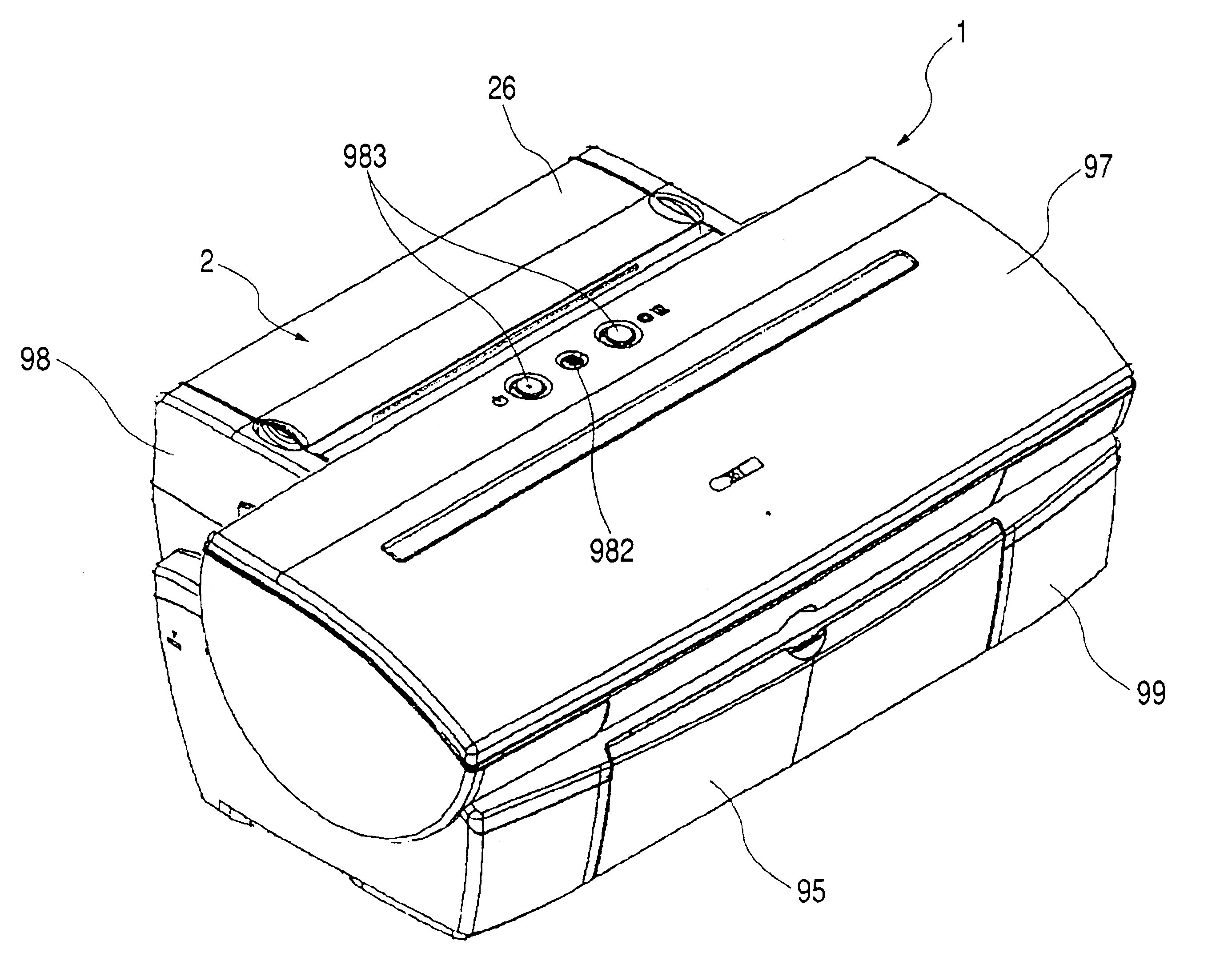
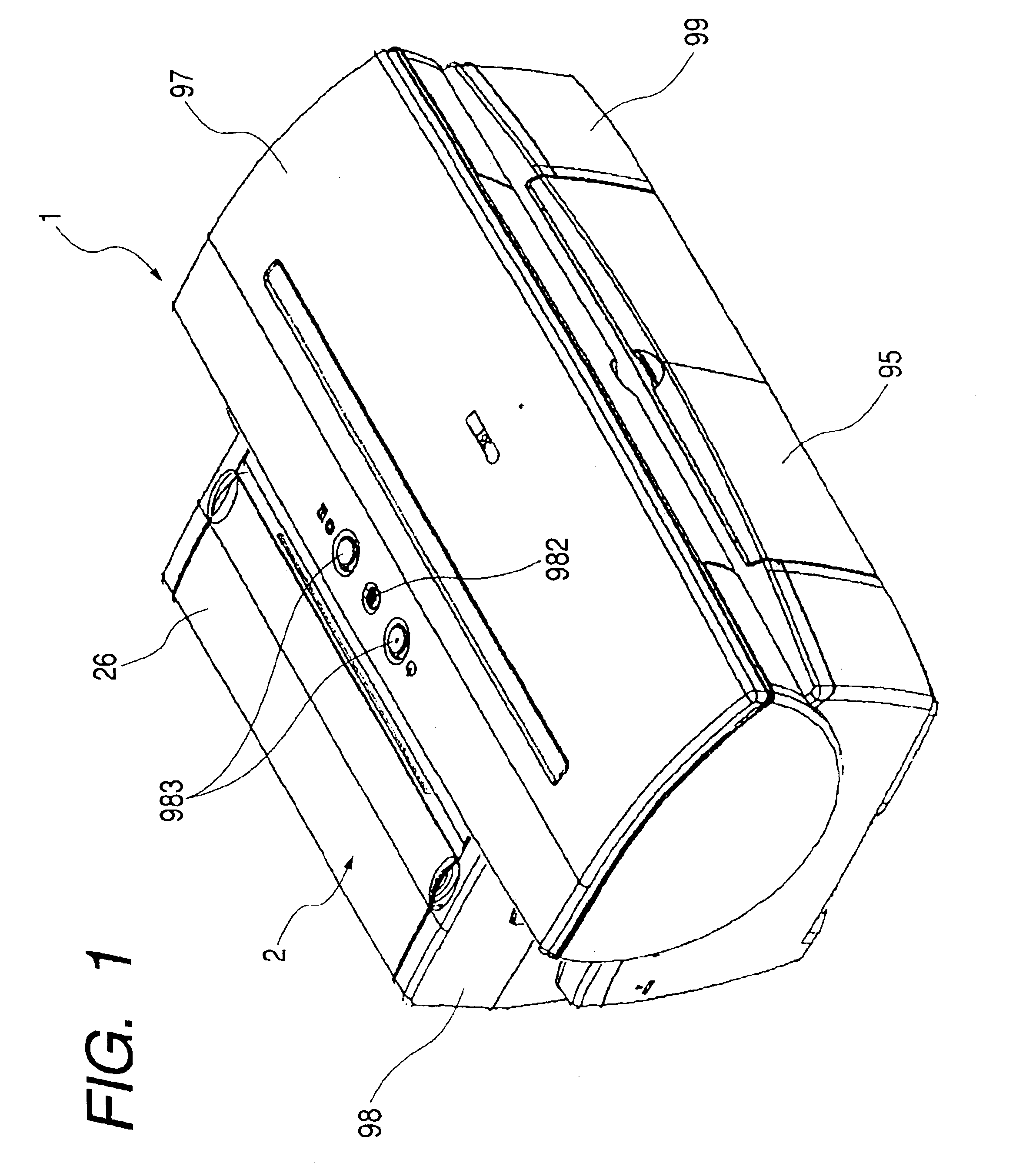
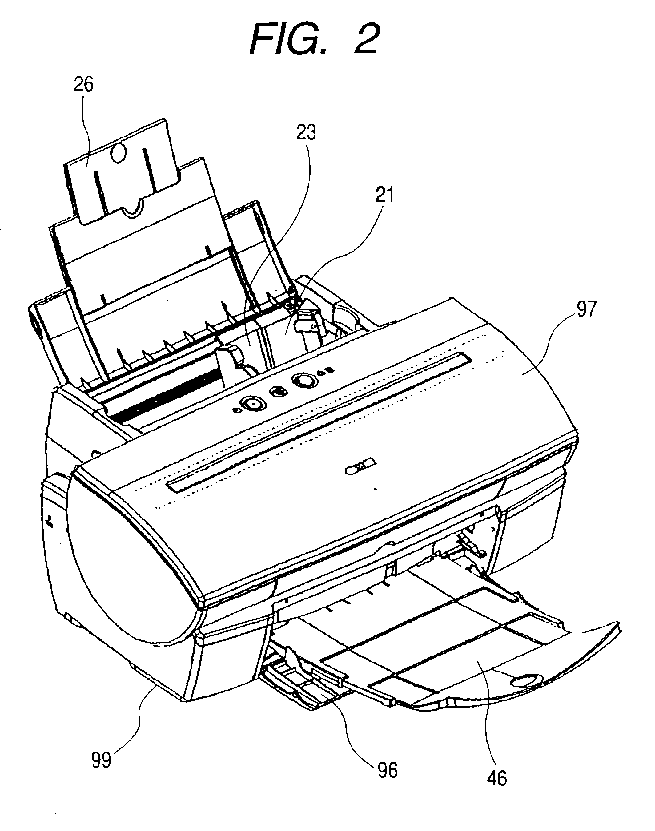
[0065]FIG. 1 is a perspective view showing an embodiment of a recording apparatus to which the present invention is applied. FIG. 2 is a perspective view showing the recording apparatus of FIG. 1 with a sheet feeding tray and a sheet delivery tray opened. FIG. 3 is a perspective view showing an internal mechanism of the recording apparatus of FIG. 1 as viewed from a right-hand front side. FIG. 4 is a perspective view showing an internal mechanism of the recording apparatus of FIG. 3 as viewed from a left-hand front side. FIG. 5 is a longitudinal sectional view showing the recording apparatus of FIG. 3. FIGS. 6A and 6B are perspective views respectively showing states before and after a CD transporting unit 8 is attached to the recording apparatus of FIG. 1. FIG. 7 is a perspective view showing the CD transporting unit 8 attachable to the recording apparatus of FIG. 1.

[0066]In FIGS. 1 to 5, a recording apparatus 1 according to the present invention includes: a sheet fee...

embodiment 2

(Embodiment 2)

[0134]FIG. 28 is a side view schematically showing a state of guide shaft lifting and lowering means at the general print height in the recording apparatus to which the present invention is applied, according to Embodiment 2 of the present invention. FIG. 29 is a side view schematically showing a modification as a partial modification of Embodiment 2 shown in FIG. 28. According to the structure of Embodiment 1 as described above, upon the control on the position in height of the guide shaft 52, the positional detection using the sensor etc. is not performed. That is, as for the general print height and the CD print height, the control is performed by the abutment of the eccentric cam R 521 and the chassis abutment portion 525. Further, as for the cardboard print height, the control is performed by the abutment of the eccentric cam L 522 and the carriage 50. On the contrary, according to the structure of Embodiment 2 shown in FIG. 28, instead of the positional detection...

embodiment 3

(Embodiment 3)

[0137]FIG. 30 is a side view schematically showing a state of guide shaft lifting and lowering means at the general print height in the recording apparatus to which the present invention is applied, according to Embodiment 3 of the present invention. According to Embodiment 3 shown in FIG. 30, the general printing position in height of the guide shaft 52 is detected by the cam rotation position sensor 523 and at the same time, the pulse motor is used as the carriage lifting motor 58. Embodiment 3 shown in FIG. 30 differs from Embodiment 1 or 2 above in this point but has substantially the same structure except for this point. According to Embodiment 3 shown in FIG. 30, the control on the position in height of the guide shaft 52 after the detection of the general print height can be made in such a way as to change position of the guide shaft to any position in height according to the pulse frequency applied to the carriage lifting motor 58 as the pulse motor. Also, the ...


PUM


Abstract

To provide a recording apparatus for recording on a sheet by a recording head, including: a carriage for carrying the recording head and moving in a direction crossing a sheet transporting direction; a guide shaft for guiding a movement of the carriage; and a guide shaft lifting mechanism for changing a position in height of the guide shaft at three or more stages without changing a position of the guide shaft in the sheet transporting direction.

Description

BACKGROUND OF THE INVENTION[0001]1. Field of the Invention[0002]The present invention relates to a recording apparatus of a printing apparatus, an image forming apparatus, or the like. In particular, the invention relates to a recording apparatus capable of recording on recording materials having different thicknesses while setting a gap between recording means such as a recording head and the recording material as an appropriate value.[0003]2. Related Background Art[0004]Up to now, various recording materials have been proposed, on which the recording apparatus of the printing apparatus, the image forming apparatus, etc. performs recording. The above recording materials include compact recording materials with a large thickness, such as a CD-R, a DVD, and a card (hereinafter, collectively referred to as compact disc or CD). In the existing general-purpose recording apparatuses, assuming that a transport path for cut paper is adapted for recording on the recording material such as C...

Claims


Application Information

Patent Timeline
IPC IPC(8): B41J25/308
CPCB41J25/3088B41J25/308
Inventor UCHIDA, KOTAUCHIDA, HARUOIKEDA, YASUHIKO
Owner CANON KK
Why Eureka
Try Eureka