Dispensing package
a technology for dispensing packages and packaging, applied in the direction of instruments, apparatus for dispensing discrete objects, other domestic objects, etc., can solve the problems of high cost, troublesome user keeping of batteries, and insufficient demand for conventional shrink-packages or blister-packages
- Summary
- Abstract
- Description
- Claims
- Application Information
AI Technical Summary
Benefits of technology
Problems solved by technology
Method used
Image
Examples
embodiment 1
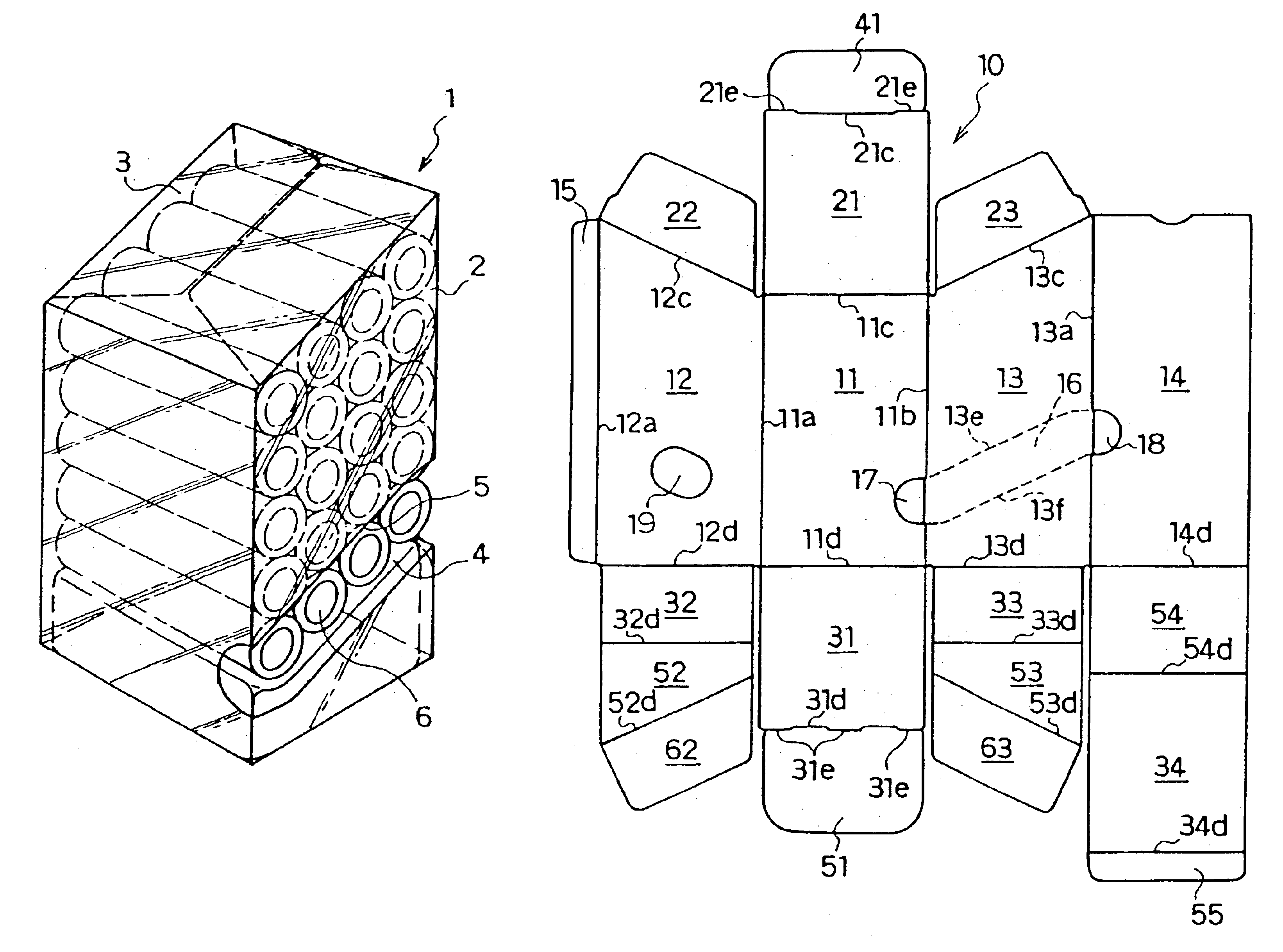
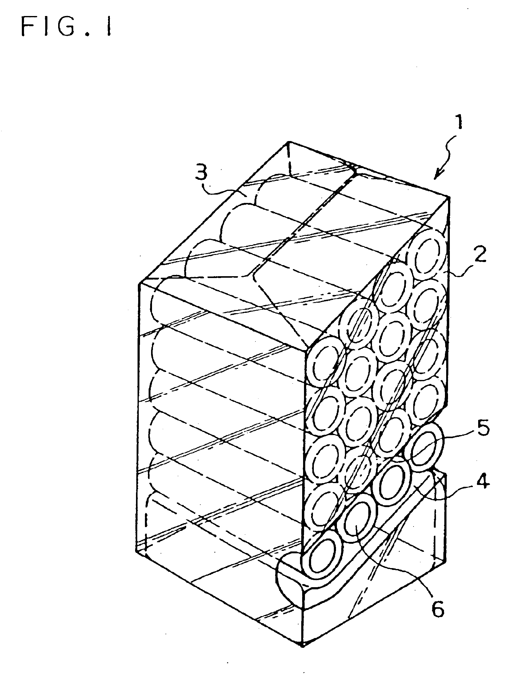
[0039]FIG. 1 shows an example of a dispensing package, and FIG. 2 shows, as a unit package for articles, a unit package 6 of a shrink-package made of a transparent resin tube 8 in which four cylindrical AA size batteries 7, for instance, are aligned in parallel with each other and packed by heat-shrinkage of the resin tube.
[0040]The dispensing package 1 comprises a square-tubular case 2 for stacking a plurality of unit packages 6 and a lid 3 which closes an upper opening of the case. A base 4 is inserted into a bottom portion of the case 2. The base 4 is made of plastic and formed into a square-tubular shape having an open bottom surface and a top surface being inclined so that a front side is lower and a rear side is higher. The unit packages 6 are stacked on the base 4 in the case 2 in such a way that they are inclined so that their front side is lower. An extracting outlet 5 for extracting the unit package in the lowest position is formed on the right side wall of the case 2. The...
embodiment 2
[0043]In this embodiment, the base portion according to Embodiment 1 is also assembled by a sheet constituting a dispensing package.
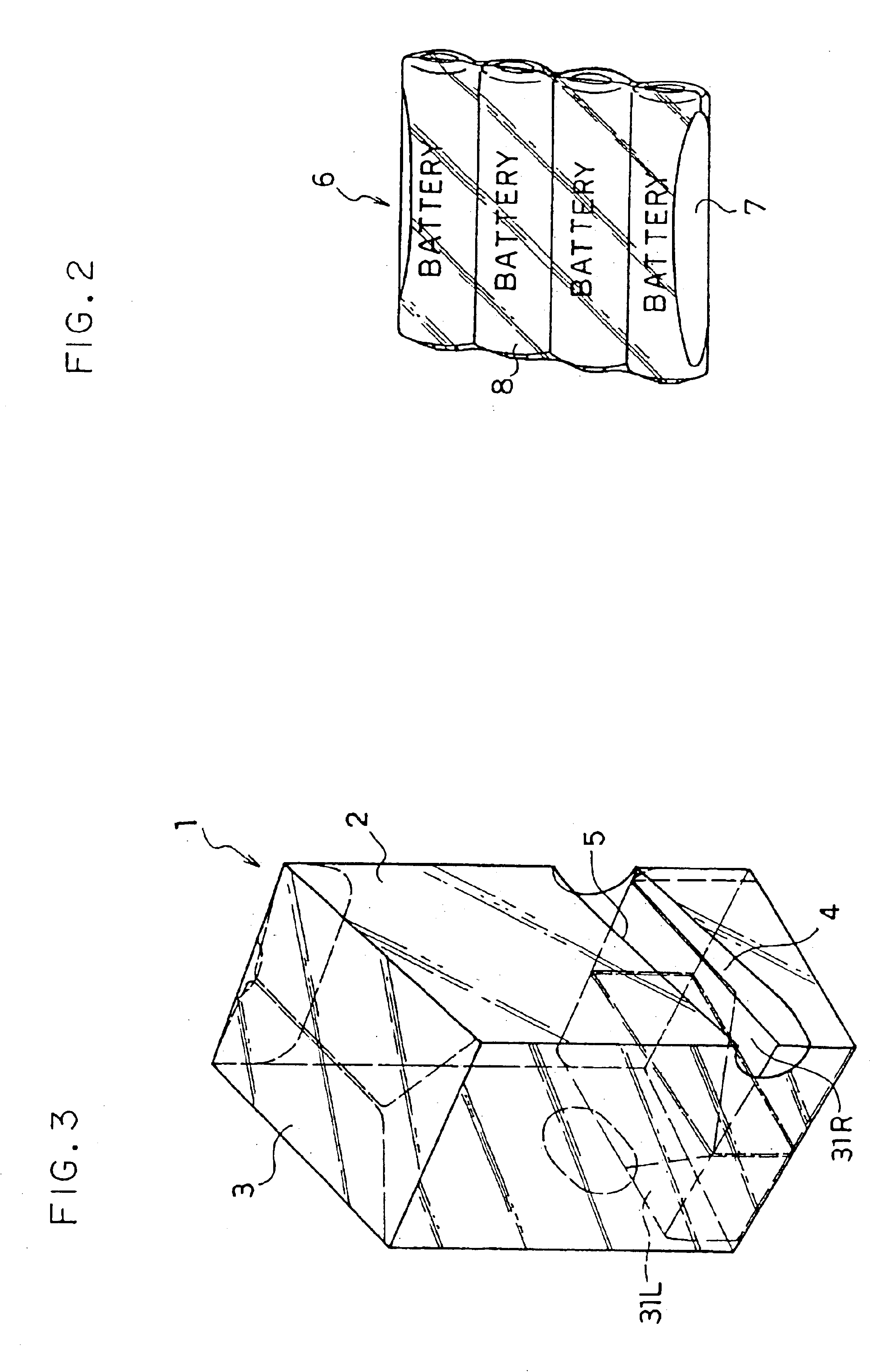
[0044]FIG. 3 illustrates an assembled dispensing package and FIG. 4 is an exploded view of a sheet constituting the package.
[0045]A sheet 10 constituting the dispensing package is made of a sheet of plastic or paper punch-processed by using a specified mold, and folding marks and perforations that are to be described later are formed on the sheet at the same time.
[0046]Numeral 11 denotes a front wall and a left side wall 12 is connected via a folding mark 11a to the left of the front wall 11 and a right side wall 13 via a folding mark 11b on the right of the front wall 11, respectively. A rear wall 14 is connected to further right to the right side wall13 via a folding mark 13a, and a margin for paste 15 to the left side wall 12 via a folding mark 12a.
[0047]An upper wall 21 and a bottom wall 31 are connected to above and below, respectively, of the fro...
embodiment 3
[0064]The present embodiment illustrates an example in which the base portion for stacking the unit packages thereon is formed separately from the sheet for assembling the package. FIG. 8 is a perspective view of an assembled package, FIG. 9 is a perspective view showing a base to be inserted into the bottom portion of the package, and FIG. 10 is a perspective view showing a bottom wall of the package.
[0065]First, a sheet constituting the package will be explained with reference to the exploded view as shown in FIG. 11.
[0066]Numeral 111 denotes a front wall. A left side wall 112 is provided on the left side of the front wall 111 via a folding mark 111a, and to the left of the left side wall 112, a margin for paste 115 is provided via a folding mark 112a. A right side wall 113 is provided on the right side of the front wall 111 via a folding mark 111b, and to the right of the right side wall 113, a rear wall 114 is provided via a folding mark 113a.
[0067]On an upper portion of the fr...
PUM
| Property | Measurement | Unit |
|---|---|---|
| Transparency | aaaaa | aaaaa |
Abstract
Description
Claims
Application Information
 - R&D
- Intellectual Property
- Life Sciences
- Materials
- Tech Scout
- Unparalleled Data Quality
- Higher Quality Content
- 60% Fewer Hallucinations
Browse by: Latest US Patents, China's latest patents, Technical Efficacy Thesaurus, Application Domain, Technology Topic, Popular Technical Reports.
© 2025 PatSnap. All rights reserved.Legal|Privacy policy|Modern Slavery Act Transparency Statement|Sitemap|About US| Contact US: help@patsnap.com


