Pedestal system and method of controlling rotational and bearing stiffness

a technology of pedestal system and bearing stiffness, which is applied in the direction of antenna, antenna details, electrical apparatus, etc., can solve the problem of not describing a pedestal system that allows, and achieve the effects of low manufacturing cost, convenient and efficient manufacturing and marketing, and durable and reliable construction

Inactive Publication Date: 2005-07-05
MENAHEM ISRAEL
View PDF4 Cites 34 Cited by
  • Summary
  • Abstract
  • Description
  • Claims
  • Application Information

AI Technical Summary

Benefits of technology

[0015]It is therefore an object of the present invention to provide a new and improved pedestal system which has all of the advantages of the prior art pedestals and supports of known designs and configurations and none of the disadvantages.
[0016]It is another object of the present invention to provide a new and improved pedestal system which may be easily and efficiently manufactured and marketed.
[0017]It is further an object of the present invention to provide a new and improved pedestal system which is of durable and reliable constructions.
[0018]An even further object of the present invention is to provide a new and improved pedestal system which is susceptible of a low cost of manufacture with regard to both materials and labor, and which accordingly is then susceptible of low prices of sale to the consuming public, thereby making such pedestal system economically available to the buying public.

Problems solved by technology

While these devices fulfill their respective, particular objectives and requirements, the aforementioned patents do not describe a pedestal system that allows supporting any of a plurality of objects at any of a plurality of angular orientations.

Method used


Image

  • Pedestal system and method of controlling rotational and bearing stiffness
  • Pedestal system and method of controlling rotational and bearing stiffness
  • Pedestal system and method of controlling rotational and bearing stiffness

Examples


Embodiment Construction

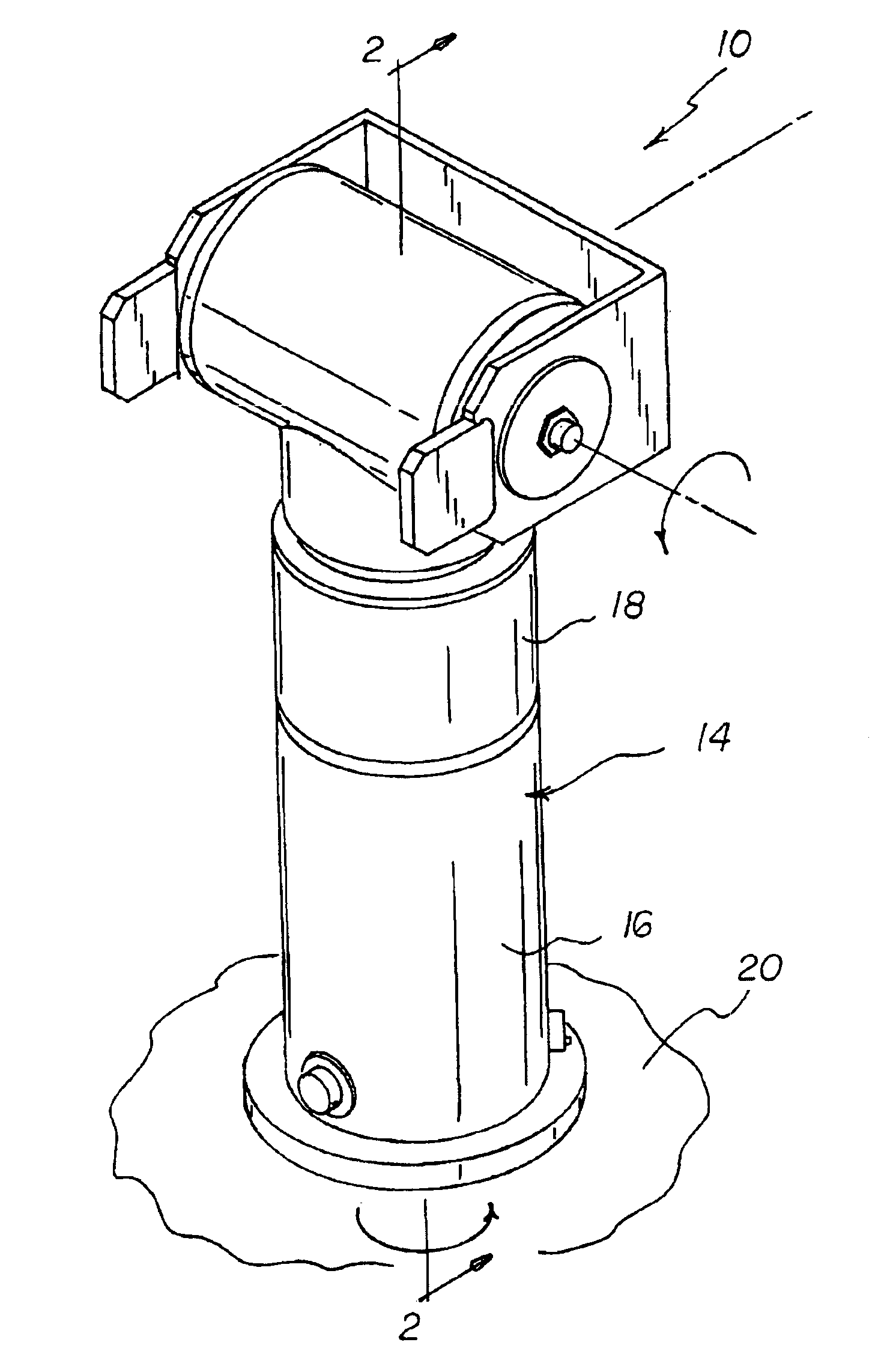
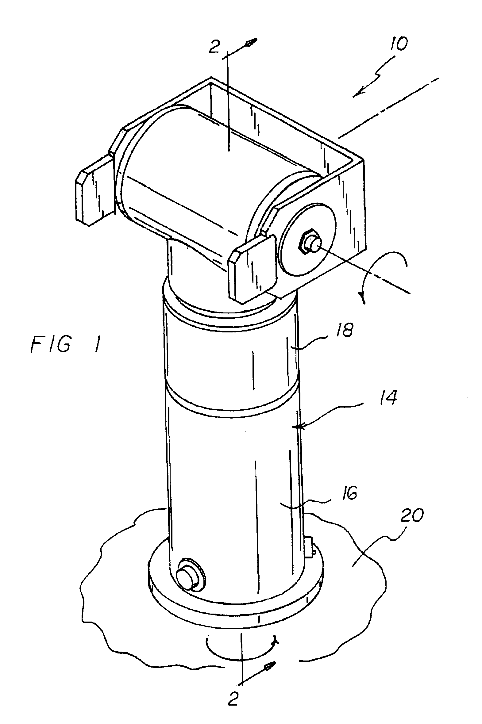
[0037]With reference now to the drawings, and in particular to FIG. 1 thereof, the preferred embodiment of the new and improved pedestal system embodying the principles and concepts of the present invention and generally designated by the reference numeral 10 will be described.

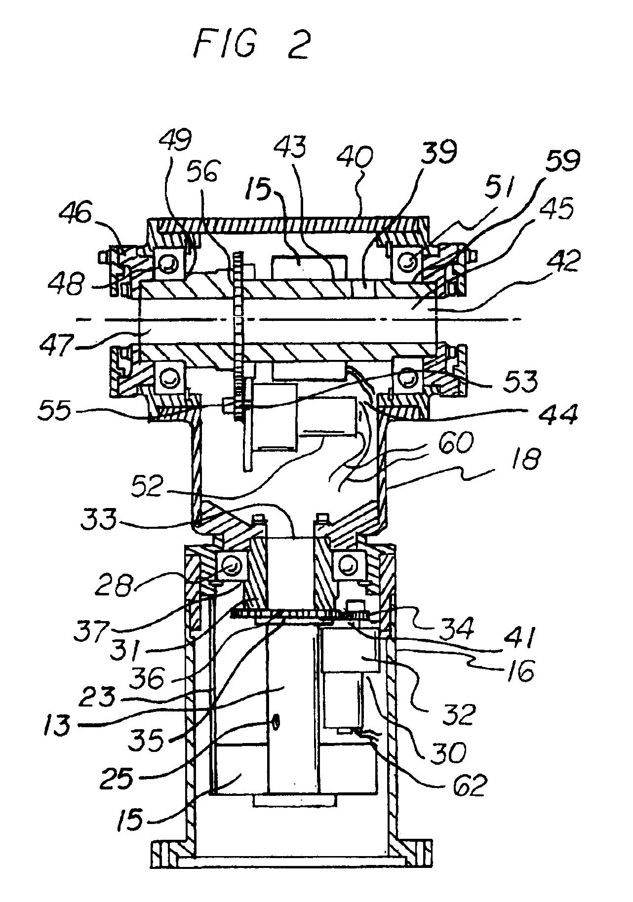
[0038]The present invention, the pedestal system 10 is comprised of a plurality of components. Such components in their broadest context include a base, a lower motor, a horizontal shaft, and an upper motor. Such components are individually configured and correlated with respect to each other so as to attain the desired objective.

[0039]A pedestal system 10 for supporting any of a plurality of objects at any of a plurality of angular orientations. The system comprises several components in combination.

[0040]First provided is a base 14 having a lower vertical cylinder 16 and an upper vertical cylinder 18. Each cylinder has an interior surface and an exterior surface. The lower vertical cylinder is fixedly suppor...


PUM


Abstract

A pedestal system comprises a base having a lower cylinder and an upper rotatably supported with respect to the lower vertical cylinder. A lower motor is coupled between the lower and upper cylinders to selectively cause rotational motion between the cylinders. Also provided is a top-most horizontal cylinder with a rotating shaft. The shaft has a bearing coupling the top-most horizontal shaft with respect to the upper vertical cylinder. Finally, an upper motor is provided. The upper motor is coupled between the top-most horizontal shaft and upper cylinder to selectively cause a rotational motion between the top-most horizontal shaft and the upper vertical cylinders.

Description

BACKGROUND OF THE INVENTION[0001]1. Field of the Invention[0002]The present invention relates to a pedestal system and more particularly pertains to supporting any of a plurality of objects at any of a plurality of angular orientations.[0003]2. Description of the Prior Art[0004]The use of pedestals and supports of known designs and configurations is known in the prior art. More specifically, pedestals and supports of known designs and configurations previously devised and utilized for the purpose of providing variable support for objects through conventional methods and apparatuses are known to consist basically of familiar, expected, and obvious structural configurations, notwithstanding the myriad of designs encompassed by the crowded prior art which has been developed for the fulfillment of countless objectives and requirements.[0005]By way of example, U.S. Pat. No. 2,877,459 to Brown discloses an antenna pedestal mount. U.S. Pat. No. 5,453,753 to Cosenza et al discloses a mechan...

Claims


Application Information

Patent Timeline
Patent Type & Authority Patents(United States)
IPC IPC(8): H01Q1/12H01Q3/00H01Q3/08
CPCH01Q1/125H01Q3/08
Inventor MENAHEM, ISRAEL
Owner MENAHEM ISRAEL
Why Eureka
Try Eureka