Protective optical filter assembly

Inactive Publication Date: 2005-07-19
OMEGA OPTICAL
View PDF14 Cites 7 Cited by
  • Summary
  • Abstract
  • Description
  • Claims
  • Application Information

AI Technical Summary

Benefits of technology

[0011]Accordingly, there is a need for an easily assembled protective optical filter assembly (also referred to herein simple as a “filter assembly”) that provides protection for thin film filters while providing adequate optical performance, and having relatively low cost of manufacture and relatively high manufacturing yields. The above need is addressed by a filter assembly according to the present invention that forms a sealed region in

Problems solved by technology

While thin film filters have many desirable qualities, they are sensitive to many physical and environmental sources of degradation or permanent damage.
For example, thin film filters may be degraded or damaged by physical contact, humidity, and abrupt temperature changes.
However, these solutions have numerous drawbacks, including wavefront distortion and/or reduction in optical efficiency due to absorption or scattering of the electromagnetic radiation by the protective material.
Furthermore, conventional optical filter assemblies have resulted in incr

Method used


Image

  • Protective optical filter assembly
  • Protective optical filter assembly
  • Protective optical filter assembly

Examples


Embodiment Construction

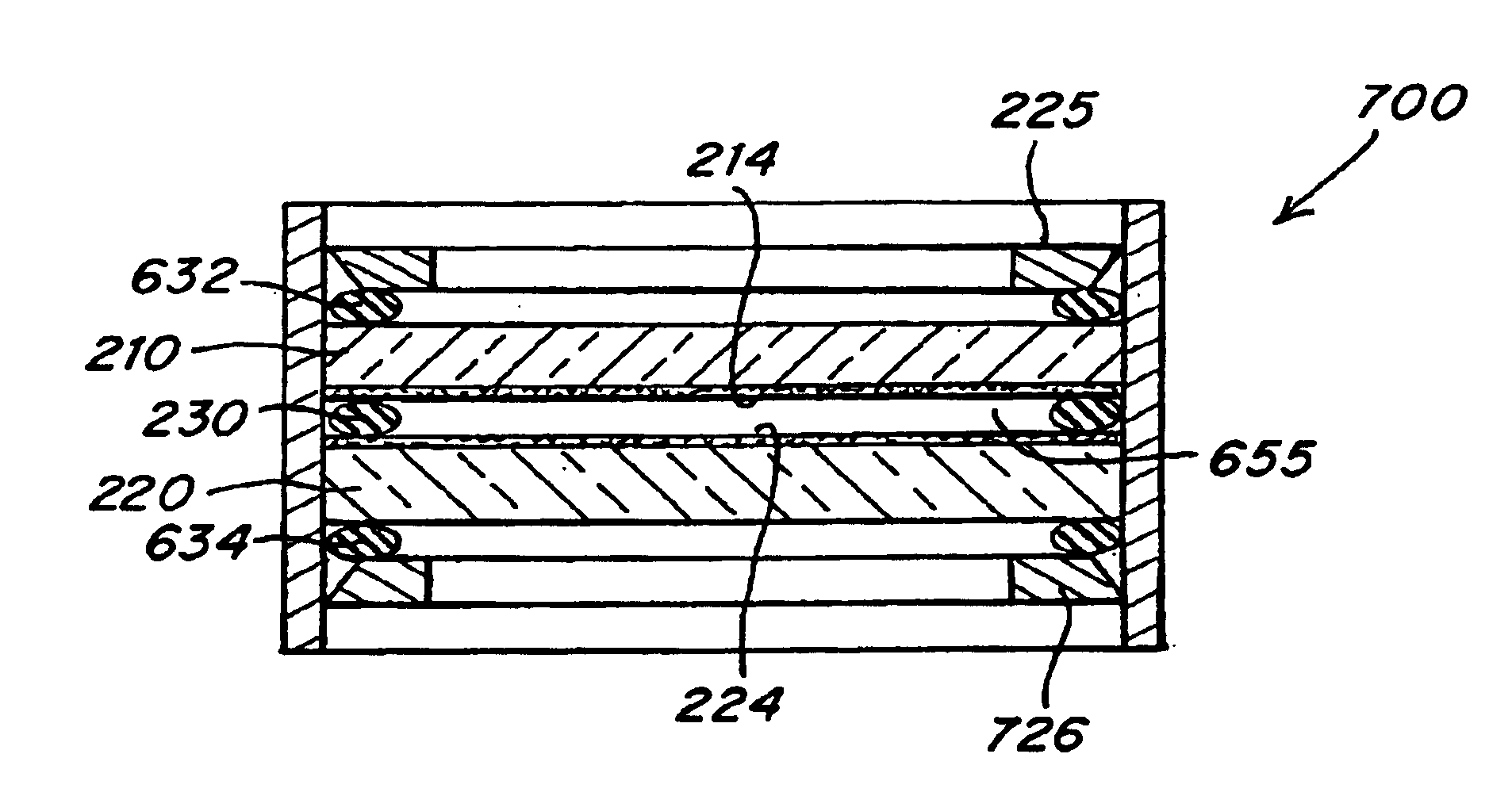
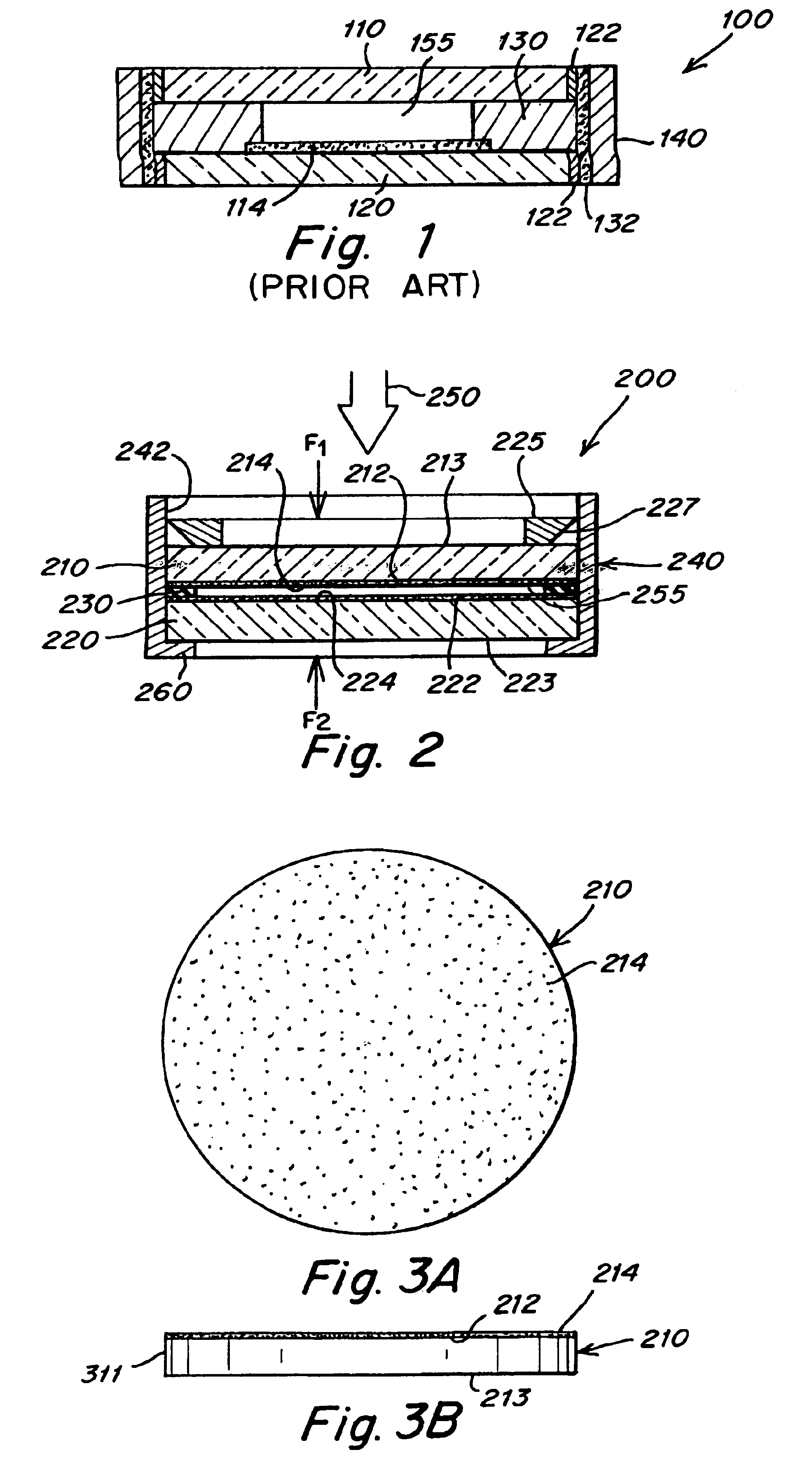
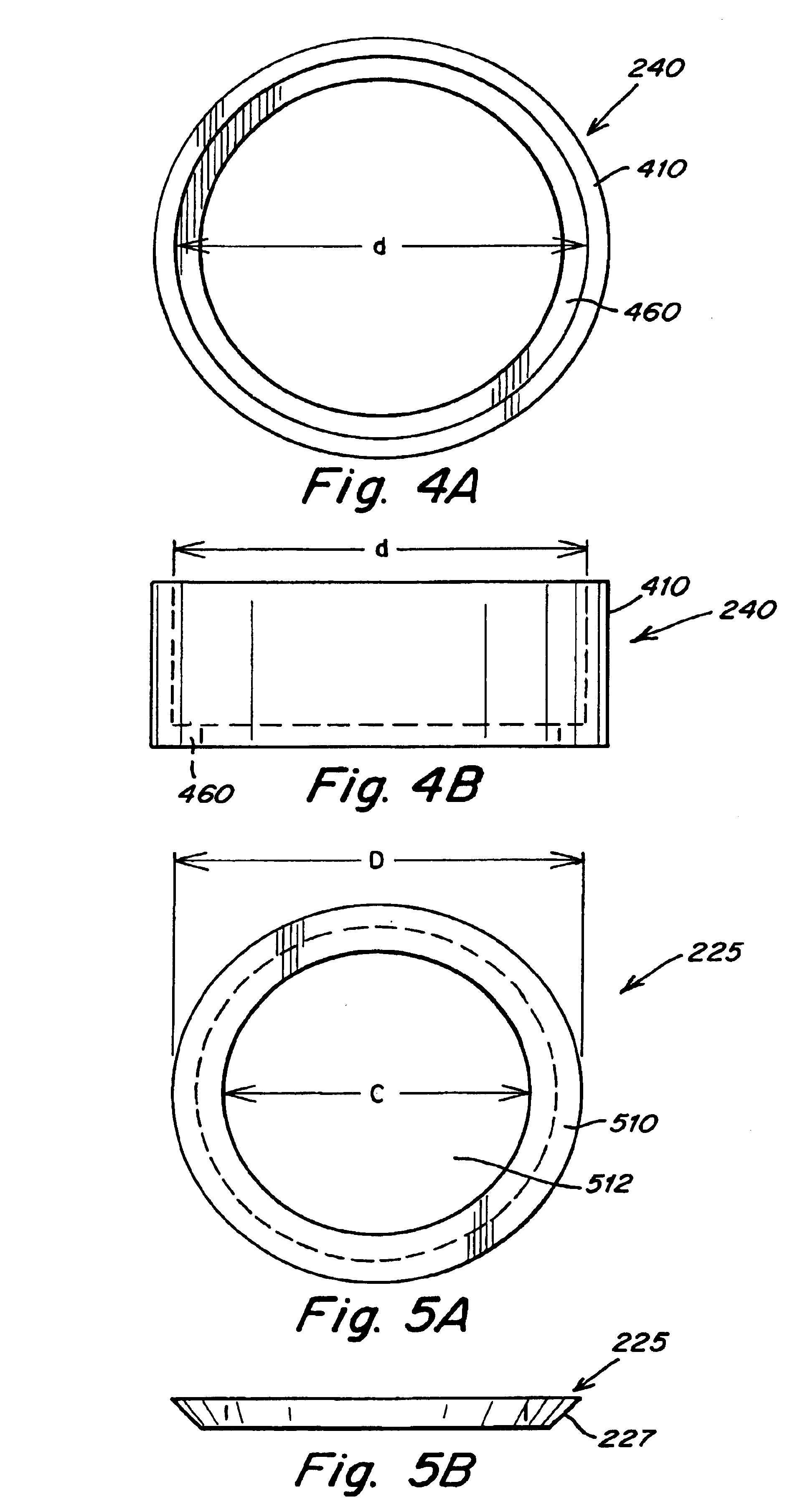
[0049]FIG. 2 is a cross-sectional side view of one example of a filter assembly 200 to filter electromagnetic radiation 250 according to some aspects of the present invention. Filter assembly 200 includes a first transparent substrate 210 and a second transparent substrate 220 disposed within a carrier 240. The term “transparent” is defined herein to mean substantially transparent to at least a selected operative wavelength or band of wavelengths of the electromagnetic radiation.

[0050]Transparent substrate 210 has a thin film filter 214 disposed on a first surface 212, and transparent substrate 220 has a thin film filter 224 disposed on a second surface 222. Optionally, a third surfaces 213 and a fourth surface 223 may be coated with an anti-reflective coating.

[0051]Transparent substrates 210 and 220 can be any suitable material sufficiently transparent to at least a portion of electromagnetic radiation 250 (i.e., the operative wavelength of filter assembly 200). Transparent substra...


PUM


Abstract

A protective optical filter assembly for thin film filters having two transparent substrates facing one another and separated by a resilient element, a sealed region is formed between the transparent substrates by applying a compressive force that compresses the resilient element. The thin film filter may be contained within a carrier. The compressive force may be generated by one or more interference-fit aperture rings or threaded apertures ring, a given aperture ring may be opposed by another such aperture ring or a fixed stop. Alternatively a snap fit carrier may be used to generate the compressive force. The sealed region may have a gas having a positive pressure or a liquid.

Description

RELATED APPLICATIONS[0001]This application claims the benefit of U.S. Provisional Application No. 60 / 348,270 filed Jan. 15, 2002, entitled “EFFICIENT FILTER ASSEMBLY,” by Johnson, et al. The entirety of the above provisional application is hereby incorporated by reference.BACKGROUND OF THE INVENTION[0002]1. Field of Invention[0003]This invention relates to optical filter assemblies providing protection from physical and / or environmental damage to optical components, and more particularly to optical filter assemblies providing protection to thin film filter components.[0004]2. Related Art[0005]Optical thin film filters (also referred to herein simply as “thin film filters”) allow selective transmission of bands of electromagnetic radiation. Optical thin film filters may provide high pass, low pass, or band pass functionality using any of a number of different thin film structures. For example, thin film filters are commonly achieved by depositing one or more refractory oxide material...

Claims


Application Information

Patent Timeline
IPC IPC(8): G02B5/20G02B7/00
CPCG02B5/20G02B7/006
Inventor JOHNSON, ROBERT L.GORAWSKI, NATALIAO'DWYER, BARRY
Owner OMEGA OPTICAL
Why Eureka
Try Eureka