Image display apparatus control system and image display system control method

Inactive Publication Date: 2005-08-02
CANON KK
View PDF28 Cites 37 Cited by
  • Summary
  • Abstract
  • Description
  • Claims
  • Application Information

AI Technical Summary

Benefits of technology

[0012]It is an object of the present invention to simplify the interface between an image display and supply source and facilitate connection in an image display control system having a supply sourc

Problems solved by technology

When, however, many signal cables are connected to the television receiver, the back surface of the television receiver becomes very complicated, and the television receiver must be installed with sufficient clearance at the back side.
For these reasons, the use of the cables is limited at a location where there is no margin on the back side of the television receiver or the back surface is in sight.
Even

Method used


Image

  • Image display apparatus control system and image display system control method
  • Image display apparatus control system and image display system control method
  • Image display apparatus control system and image display system control method

Examples


Example

[First Embodiment]

[0104]FIG. 1 is a view for explaining the basic arrangement according to the first embodiment of the present invention. In FIG. 1, reference numeral 1 denotes an image display which has a wall-mounted thin structure in this embodiment; and 2, a terminal which outputs display data and acoustic data to the image display 1 in accordance with synchronous bidirectional serial data (to be described later), and comprises a tuner for receiving a television program, as will be described later.

[0105]Reference numeral 3 denotes a video cassette recorder serving as a supply source of an image and acoustic signal to the terminal 2; 4, an LD / DVD player for playing back a laser disk or DVD disk; and 5, an STB for receiving and selecting a digital program.

[0106]The terminal 2 is connected to connection cables extending from the supply sources for the respective image signals and the like, and to a terrestrial television broadcasting (VHS / UHS) antenna line and satellite broadcastin...

Example

[Second Embodiment]

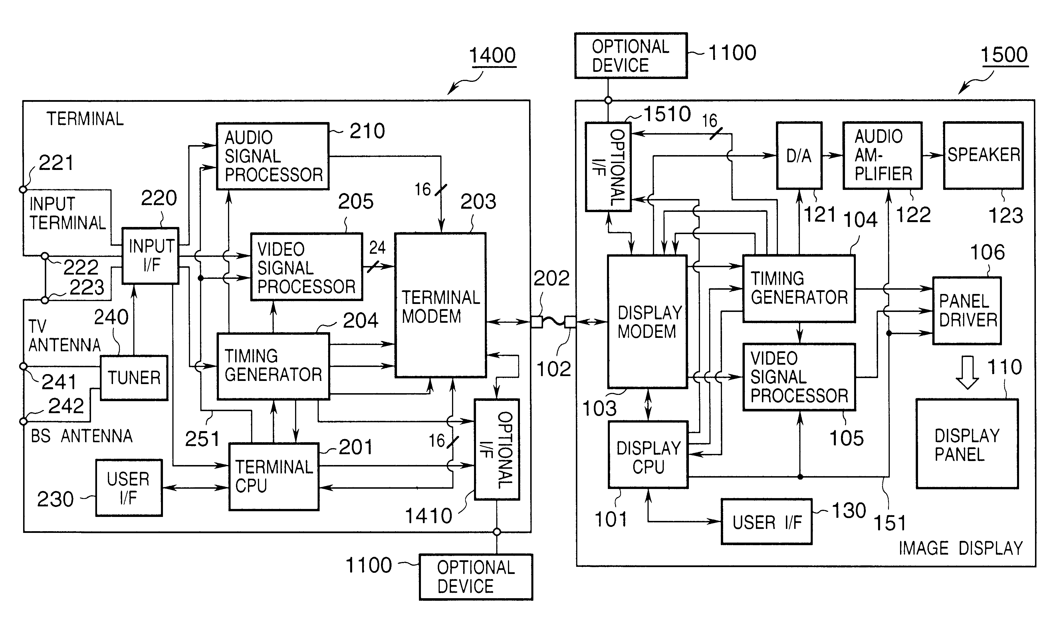
[0253]In the first embodiment, the terminal 2 is connected to one image display 1, and the image display 1 is not connected to any other device. However, the present invention is not limited to this. Another optional device may be connected to one terminal or image display. For example, a video printer is connected to hard-copy image data displayed on the image display. Note that the second embodiment is the same as the first embodiment except for the following arrangement, and a detailed description thereof will be omitted.

[0254]The second embodiment according to the present invention in which another optional device, e.g., a video printer, is connected to one terminal or image display, will be described with reference to FIGS. 26 to 28. In the second embodiment, the same reference numerals as in the first embodiment denote the same parts, and a detailed description thereof will be omitted. Also in the second embodiment, exchange of various data between the image...

Example

[Third Embodiment]

[0271]In the second embodiment, the dedicated modem and connection line are employed for the optional device 1100 in order to connect the optional device 1100. However, when the optional device is not one which need not emergently transmit / receive a large amount of information in real time, for example, when the optional device is a video printer, the dedicated modem and connection line need not be necessarily adopted for the optional device 1100.

[0272]Even when the optional device is connected to the image display, information for the optional device is controlled to be multiplexed and communicated using the idle time of information communication between the terminal and image display.

[0273]The third embodiment according to the present invention in which communication between the optional device and terminal is executed during the idle time of communication between the terminal and image display even when the optional device is connected to the image display will ...


PUM


Abstract

An arrangement including a terminal for outputting at least a pair of video and acoustic signals, and a display for receiving the signals from the terminal and displaying a corresponding image, utilizes (1) a terminal modem including a multiplexer for time division multiplexing video and acoustic signals, and an input/output driver circuit for outputting the multiplexed signal, and (2) a display modem including an input/output driver circuit for inputting the multiplexed signal output from the terminal, and a demultiplexer for demultiplexing the input multiplexed signal into corresponding video and acoustic signals. The display can be connected to an optional device, and the optional device is also controlled by the terminal.

Description

FIELD OF THE INVENTION[0001]The present invention relates to an image display apparatus control system and image display system control method capable of displaying input image information on an image display apparatus via an interface with a simple structure.BACKGROUND OF THE INVENTION[0002]FIG. 49 shows an arrangement used to display various images on a television receiver for receiving and displaying a conventional television program. As shown in FIG. 49, the television receiver is conventionally connected to a terrestrial television broadcasting (VHS / UHF) antenna line and satellite broadcasting (BS) antenna line through cables extending from other display information supply sources, the television receiver is connected to signal cables, such as a video signal line and acoustic signal line from a video cassette recorder, a video signal line and acoustic signal line from an LD / DVD playback apparatus, and a signal line from a digital broadcasting receiver (STB).[0003]A video signal...

Claims


Application Information

Patent Timeline
IPC IPC(8): H04N9/12H04N5/44H04N5/445G09G3/20H04N9/30H04N5/66H04N5/46H04N7/015G06F3/14G09G5/00
CPCH04N5/44H04N5/44513H04N9/12G06F3/1423G09G5/006G09G2370/04H04N5/4401H04N5/46H04N5/66H04N9/30H04N21/4122H04N21/42202H04N21/426H04N21/4318H04N21/43615H04N21/4363H04N21/4396H04N21/4398H04N21/4402H04N21/4621H04N21/4622H04N21/47H04N21/472H04N21/6581H04N21/8352H04N7/015
Inventor YAMAZAKI, TATSUROABE, NAOTOMORI, MAKIKO
Owner CANON KK
Why Eureka
Try Eureka