Container with flexible panels

a container and flexible technology, applied in the field of pressure-adjusting containers, can solve the problems of high stress points at the top and bottom edges of the container, the thin sidewall of the container deforms or collapses, and the container is more likely to fail during storage or handling

Inactive Publication Date: 2005-08-30
MELROSE DAVID MURRAY
View PDF36 Cites 56 Cited by
  • Summary
  • Abstract
  • Description
  • Claims
  • Application Information

AI Technical Summary

Problems solved by technology

However, a container that is used for hot fill applications is subject to additional mechanical stresses on the container that result in the container being more likely to fail during storage or handling.
For example, it has been found that the thin sidewalls of the container deform or collapse as the container is being filled with hot fluids.
However, the inward flexing of the panels caused by the hot fill vacuum creates high stress points at the top and bottom edges of the panels, especially at the upper and lower comers of the panels.
These stress points weaken the portions of the sidewall near the edges of the panels, allowing the sidewall to collapse inwardly during handling of the container or when containers are stacked together.
“Hot fill” applications impose significant and complex mechanical stress on a container structure due to thermal stress, hydraulic pressure upon filling and immediately after capping, and vacuum pressure as the fluid cools.
The hot fluid will cause the container walls to soften and then shrink unevenly, causing distortion of the container.
As the liquid, and the air headspace under the cap, subsequently cool, thermal contraction results in partial evacuation of the container.
The vacuum created by this cooling tends to mechanically deform the container walls.
The amount of “flex” available in each panel is limited, however, and as the limit is approached there is an increased amount of force that is transferred to the side walls.
This causes stress to be placed on the container side wall.
There is a forced outward movement of the heat panels, which can result in a barreling of the container.
With the panel being generally flat, however, the amount of movement is limited in both directions.
It is disclosed that too much curvature would prevent this, however.
The amount of flex is limited, however, due to the need to keep a shallow curvature on the radial profile of the panels.
Thus, such a container structure increases the amount of force supplied to each of the two panels, thereby increasing the amount of flex force available.
Even so, the convex portion of the panels must still be kept relatively flat, however, or the vacuum force cannot draw the panels into the required concavity.
Further, it is generally considered impossible for a shape that is convex in both the longitudinal and horizontal planes to successfully invert, anyhow, unless it is of very shallow convexity.
Still further, the panels cannot then return back to their original convex position again upon release of vacuum pressure when the cap is removed if there is any meaningful amount of convexity in the panels.
The panel is then unable to reverse in direction as there is no longer the influence of heat from the liquid to soften the material and there is insufficient force available from the ambient pressure.
Additionally, there is no longer assistance from the memory force that was available in the plastic prior to being flipped into a concave position.
When the container stores a viscous substance, such as jelly, jam, preserves, or heavy syrup, the viscous substance may become trapped in these crevices and recesses.
Accordingly, a consumer may have difficulty accessing and removing a viscous substance from the container.

Method used


Image

  • Container with flexible panels
  • Container with flexible panels
  • Container with flexible panels

Examples


Embodiment Construction

[0035]A preferred embodiment of the invention is discussed in detail below. While specific exemplary embodiments are discussed, it should be understood that this is done for illustration purposes only. A person skilled in the relevant art will recognize that other components and configurations can be used without parting from the spirit and scope of the invention.

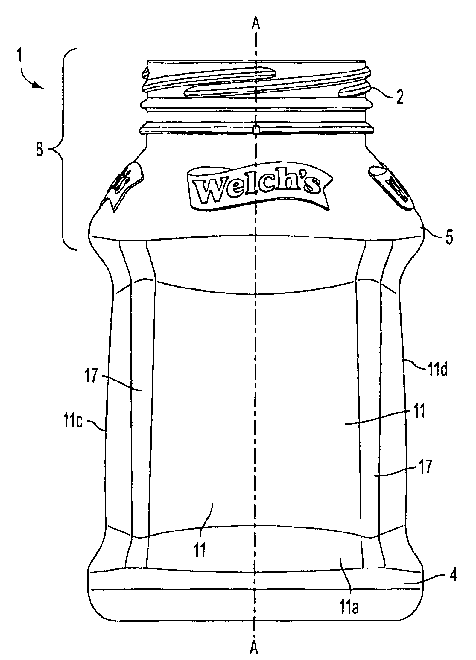
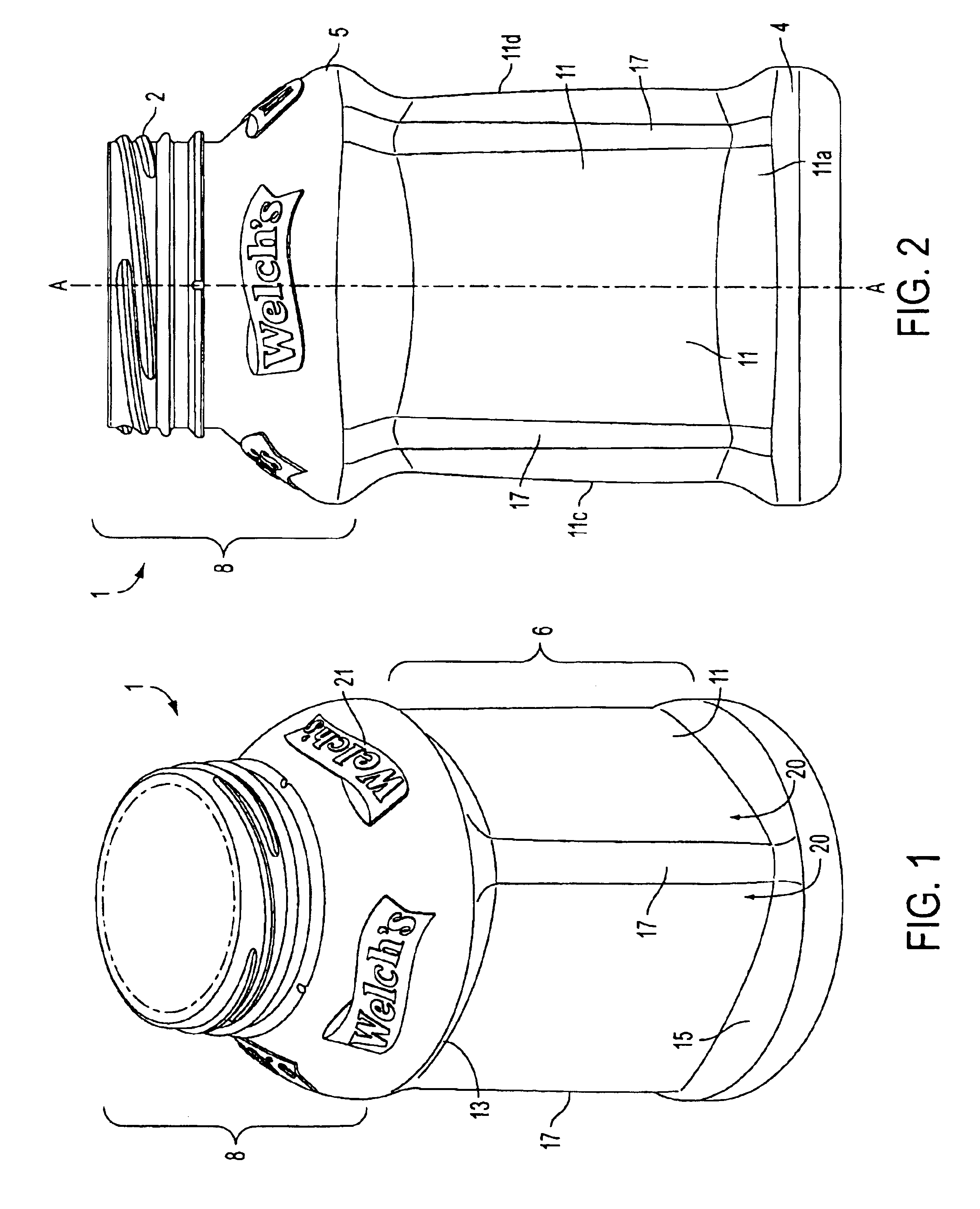
[0036]Referring now to the drawings, a preferred embodiment of a container incorporating flexible side panels is indicated generally in FIGS. 1 and 2, as generally having many of the well known features of hot-fill containers. The container 1 comprises a base 4 for supporting the container 1. The container 1 has a longitudinal axis (A—A) when the container 1 is standing upright on its base 4. A body 6 extends upwardly from the base 4.

[0037]A top portion 8 finishes upwardly from the body 6 and may include a threaded neck 2 for filling and dispensing fluid. Neck 2 also is sealable with a cap (not shown). The preferred contain...


PUM


Abstract

A container having a central longitudinal axis, the container including at least one deflectable flexible panel, the flexible panel projecting from the longitudinal axis to pass through at least three curves including a first curve having a first constant radius, a second curve having a second varying radius, and a third curve having a third constant radius that is lesser than the first radius.

Description

BACKGROUND OF THE INVENTION[0001]1. Field of the Invention[0002]The present invention generally relates to a pressure-adjustable container, and more particularly to such containers that are typically made of polyester and are capable of being filled with hot liquid. It also relates to an improved sidewall construction for such containers.[0003]2. Related Art[0004]The use of blow molded plastic containers for packaging “hot fill” substances is well known. However, a container that is used for hot fill applications is subject to additional mechanical stresses on the container that result in the container being more likely to fail during storage or handling. For example, it has been found that the thin sidewalls of the container deform or collapse as the container is being filled with hot fluids. In addition, the rigidity of the container decreases immediately after the hot fill liquid is introduced into the container. As the liquid cools, the liquid shrinks in volume which, in turn, p...

Claims


Application Information

Patent Timeline
Patent Type & Authority Patents(United States)
IPC IPC(8): B65D1/02
CPCB65D1/0223B65D2501/0081Y10S215/90
Inventor TRUDE, GREG
Owner MELROSE DAVID MURRAY
Why Eureka
Try Eureka