

High-voltage electric rotating machine
a high-voltage electric, rotating machine technology, applied in synchronous machines, windings, dynamo-electric components, etc., can solve the problems of large voltage difference between conductors, more overlap of conductors, and problems in insulating performance, so as to facilitate segment assembly operations and improve slippage
- Summary
- Abstract
- Description
- Claims
- Application Information
AI Technical Summary
Benefits of technology
Problems solved by technology
Method used
Image

Examples
first embodiment
(Description of the Entire Construction)
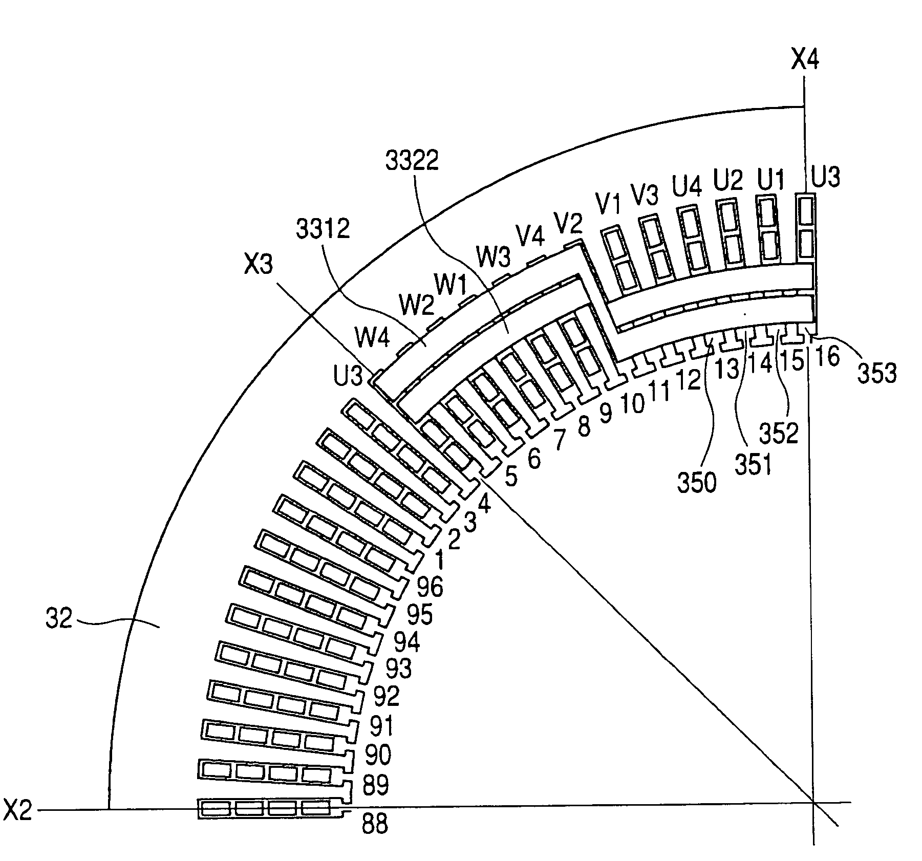
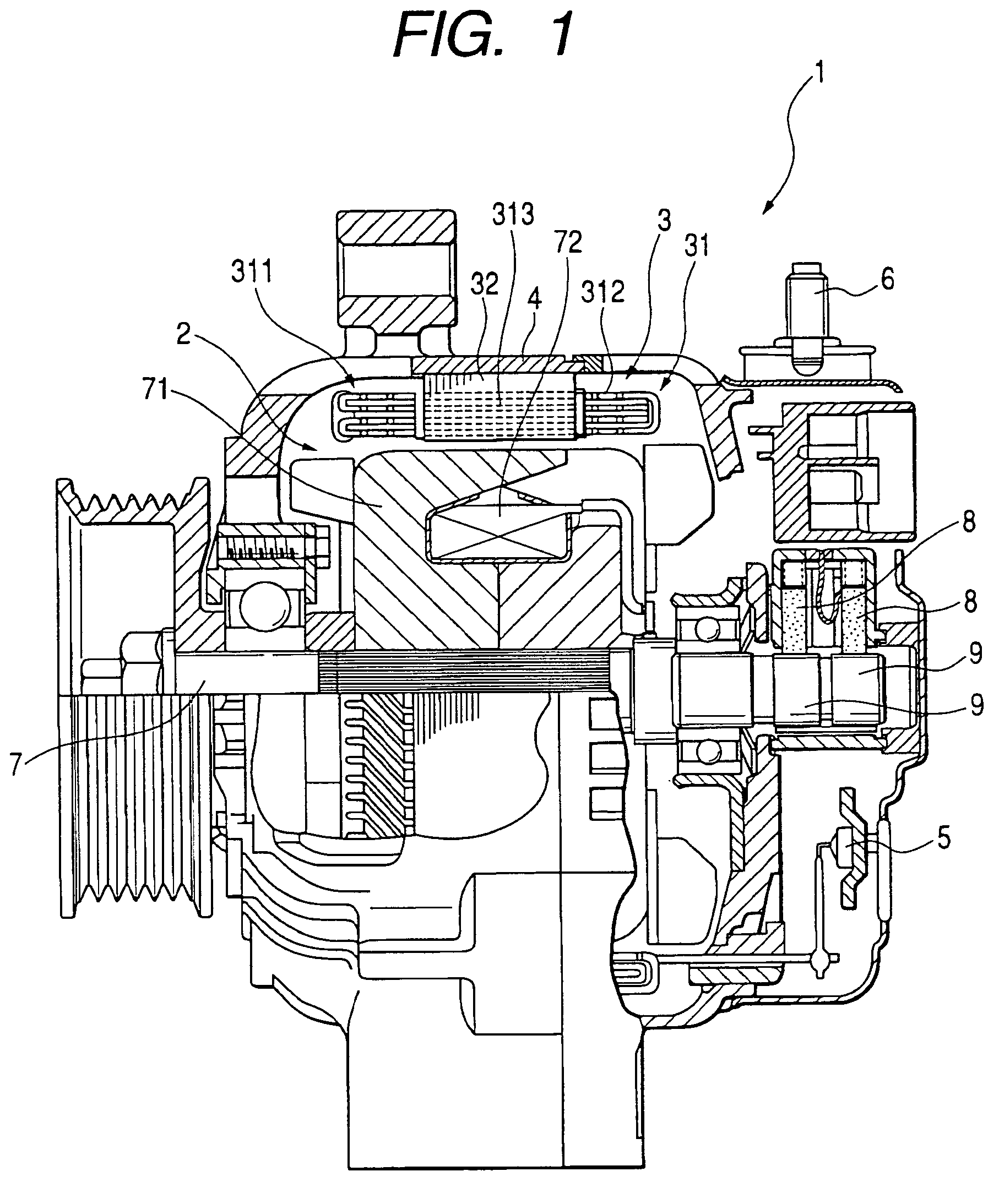
[0065]In FIG. 1, a sequential segment joining stator coil type electric rotating machine, generally designated at reference numeral 1, is constructed as an AC (Alternating Current) generator comprising a rotor 2, a ring-like stator 3 forming a stator core, a housing 4, a rectifier 5 serving as a three-phase input / output terminal, an output deriving terminal 6, a rotary shaft 7, brushes 8 and slip rings 9. The stator 3 is composed of a stator coil 31 forming a stator winding and a stator core 32, with the stator core 32 being fixedly secured onto an inner circumferential surface of a circumferential wall of the housing 4 and the stator coil 31 being placed in slots of the stator core 32 in a wound condition. The rotor 2 is of a Lundell-pole type fixed to the rotary shaft 7 supported by the housing 4 to be rotatable, and is located on a radial inner side of the stator core 32, with an electromagnetic coil 72 and a pole core forming four pole pai...
second embodiment
[0128]The difference of a second embodiment of the present invention from the above-described first embodiment is the relationship among lap winding and wave winding segments and large and small segments, and the accommodation configurations of segments in slots.
[0129]A large segment is a lap winding segment, and its pair of protruding end portions are bent in circumferential directions to approach each other and are connected to protruding end portions of another small segment by means of, for example, welding.
[0130]Moreover, a small segment is a wave winding segment, and its pair of protruding end portions are bent in circumferential directions to separate from each other and are connected to the protruding end portions of another large segment by means of, for example, welding.
[0131]In regard to this matter, only the difference from the first embodiment will be described with reference to FIG. 10, and the other is the same as the first embodiment and the description thereof will ...
third embodiment
[0150]The difference of a third embodiment of the present invention from the first embodiment is the employment of a different winding specification for each phase and, accordingly, a different angle of the coil with respect to the stator core. The other is the same as the first embodiment, and the description thereof will be omitted for brevity.
[0151]In the third embodiment, three phase windings of U, V and W are star-connected as shown in FIG. 9.
[0152]For the U phase, the partial coils U1, U2, U3 and U4 are connected in series to each other to form a UA partial coil group 101, and partial coils U1′, U2′, U3′ and U4′ are similarly connected in series to each other to form a UB partial coil group 102, and further, partial coils U1″, U2″, U3″ and U4″ are connected in series to each other to form a UC partial coil group 103.
[0153]In addition, the partial coils U1, U1′ and U1″ are connected in parallel to each other. Likewise, the partial coils U2, U2′ and U″ are connected in parallel ...
PUM
 Abstract
Description
Claims
Application Information