Multi-point touch pad

Inactive Publication Date: 2006-02-07
ADREA LLC
View PDF9 Cites 157 Cited by
  • Summary
  • Abstract
  • Description
  • Claims
  • Application Information

AI Technical Summary

Benefits of technology

[0006]The present invention is directed to a multi-point touch pad device using strain gauges or comparable measurement devices for measuring location and touch pressure that ensure an accurate and precise touch on the touch pad. A multi-point touch pad device in accordance with a preferred embodiment of the invention can be made capable of sensing simultaneous, multiple touche

Problems solved by technology

Conventional touch pads are generally only capable of registering one touch at a time, and generally, are incapable of registering a touch unless the touch is in a specific location on the touch pad.
However, specifically in the case of force sensing resistors, piezoelectric sensors and capacitive touch sensors, a touch on the touch pad will not be detected unless the sensor on the touch pad is touched directly.
Consequently,

Method used


Image

  • Multi-point touch pad
  • Multi-point touch pad
  • Multi-point touch pad

Examples


Example

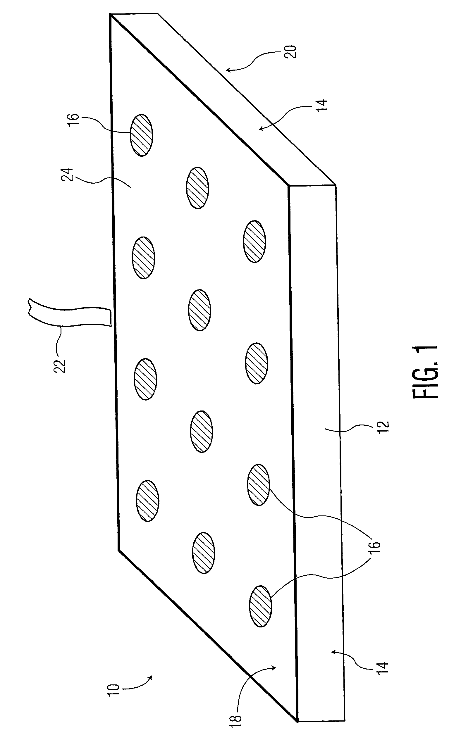
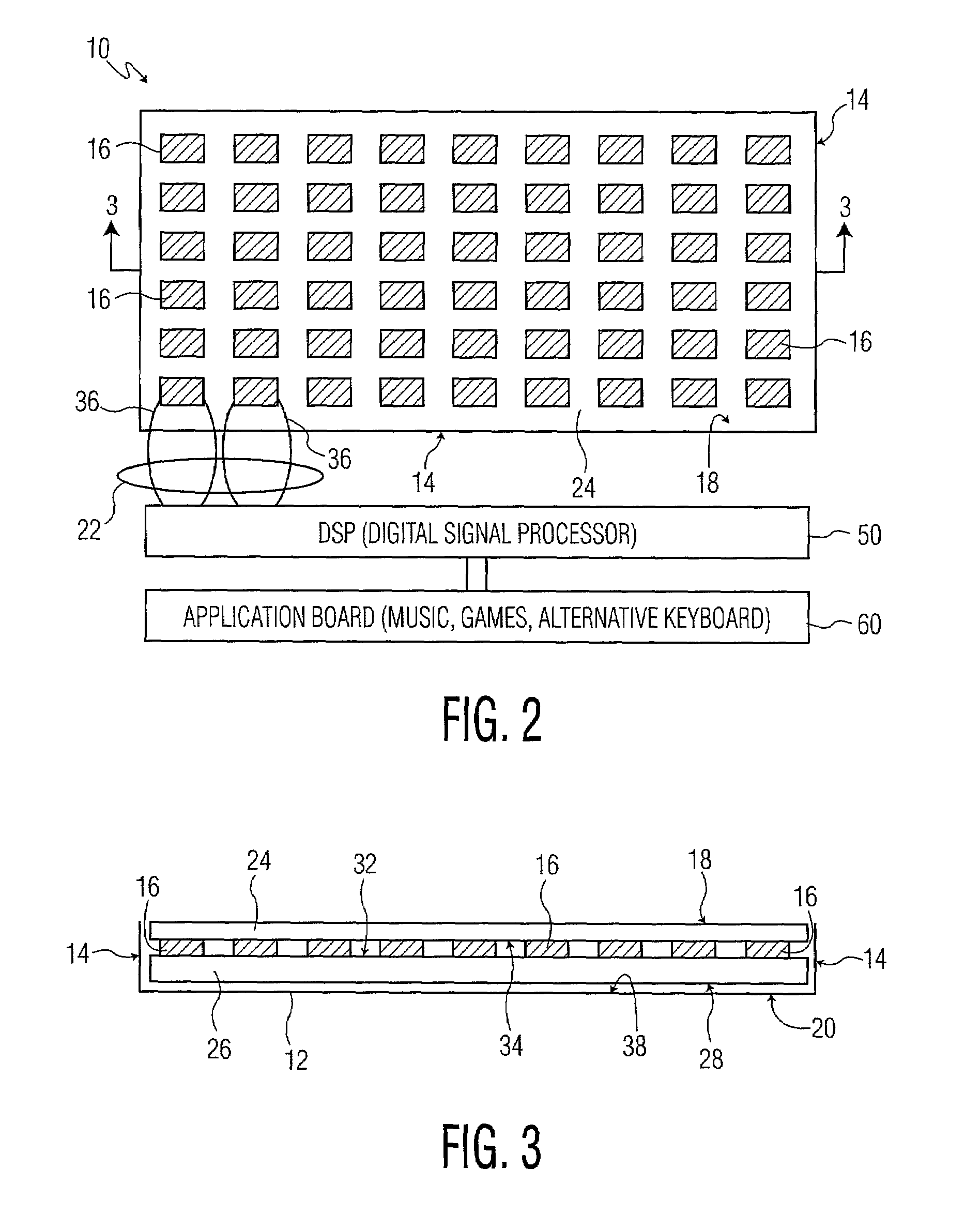
[0014]The present invention is directed to a multi-point touch pad device having a touch surface with a top surface that defines a plane, and also having a base with a surface defining a plane. At least one wall extends generally perpendicular to and away from the plane at the edge of the base. The base and at least one wall form a touch pad enclosure. A support layer made of a soft, resilient material is preferably disposed under the touch surface. The top of the support layer contains a plurality of pressure reading devices such as strain gauges that can be adhesively bonded or otherwise coupled to the top surface of the support layer, preferably in a matrix configuration. A touch layer which can be formed of a thin, film-like material is preferably disposed on top of the strain gauge matrix. The touch layer is preferably adhesively bonded or otherwise joined to the top of the strain gauge matrix. The strain gauge matrix can therefore be disposed between the support layer and the ...


PUM


Abstract

A multi-point touch pad device having a base with a top surface that defines a plane. A support layer has a top surface and a bottom surface. The top surface of the support layer contains a plurality of strain gauges that are disposed on the top surface of the support layer in a matrix configuration. A touch layer is disposed on top of the strain gauge matrix; the touch layer is joined to the top of the strain gauge matrix. Sensor wires connect the strain gauges to a processor which is programmed with an algorithm to measure the location and pressure of simultaneous, multiple touches.

Description

BACKGROUND OF THE INVENTION[0001]The invention relates generally to touch pads and more particularly to a multi-point touch pad data input device.[0002]Presently, touch pads are used in a variety of applications and in various devices. They are used on computers to control the pointing device as well as videogame controllers and security system keypads, to name a few. Conventional touch pads are generally only capable of registering one touch at a time, and generally, are incapable of registering a touch unless the touch is in a specific location on the touch pad. Generally, touch pads used with computer equipment will register an initial location where the finger touches the pad, and subsequent finger movement will be related to that initial point. Furthermore, certain computer touch pads generally may contain two special places where applied pressure corresponds to clicking a left or right mouse button. Other computer touch pads sense single taps or double taps of the finger at an...

Claims


Application Information

Patent Timeline
IPC IPC(8): G09G5/00G06F3/041G06F3/03
CPCG06F3/0414G06F2203/04104G06F3/04144G06F3/0416
Inventor LU, JIN
Owner ADREA LLC
Why Eureka
Try Eureka